
Page 224 - Automotive Engineering Powertrain Chassis System and Vehicle Body
P. 224
CH AP TER 8 .1 Types of suspension and drive
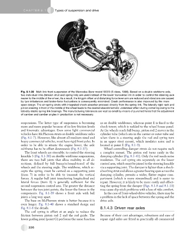
Fig. 8.1-39 Multi-link front suspension of the Mercedes-Benz model W220 (S class, 1998). Based on a double wishbone axle,
two individual links (tension strut and spring link) are used instead of the lower transverse link in order to control the steering axle
nearer to the middle of the wheel. As a result, the kingpin offset and disturbing force lever arm are reduced and vibrations are caused
by tyre imbalances and brake-force fluctuations is consequently minimized. Crash performance is also improved by the more
open design. The air-spring struts with integrated shock absorber proceed directly from the spring link. The laterally rigid rack and
pinion steering in front of the middle of the wheel leads to the desired elastokinematic understeer effect during cornering owing to the
laterally elastic spring link bearings. The manufacturing tolerances are kept so small by means of punched holes that the adjustment
of camber and camber angles in production is not necessary.
suspensions. The latter type of suspension is becoming as on double wishbones, whereas point E is fixed in the
more and more popular because of its low friction levels shock tower, which is welded to the wheel house panel.
and kinematic advantages. Even some light commercial As the wheels reach full bump, piston rod 2 moves in the
vehicles have McPherson struts or double wishbone axles cylinder tube (which sits in the carrier or outer tube and
(Fig. 8.1-7). However, like almost all medium-sized and when there is a steering angle the rod and spring turn
heavy commercial vehicles, most have rigid front axles. In in an upper strut mount, which insulates noise and is
order to be able to situate the engine lower, the axle located at point E (Fig. 8.1-9).
subframe has to be offset downwards (Fig. 8.1-37). Wheel controlling damper struts do not require such
The front wheels are steerable; to control the steering a complex mount. The piston rod turns easily in the
knuckle 5 (Fig. 8.1-38) on double wishbone suspensions, damping cylinder (Fig. 8.1-41). Only the rod needs noise
there are two ball joints that allow mobility in all di- insulation. The coil spring sits separately on the lower
rections, defined by full bump/rebound-travel of the control arm, which must be joined to the steering knuckle
wheels and the steering angle. The wishbone, which ac- via a supporting joint. The damper is lighter than a shock-
cepts the spring, must be carried on a supporting joint absorbing strut and allows a greater bearing span across the
(item 7) in order to be able to transmit the vertical damping cylinder, permits a wider, flatter engine com-
forces. A regular ball joint transferring longitudinal and partment (which is more streamlined) and is easier to
lateral forces (item 8) is generally sufficient for the repair. However, it is likely to be more costly and offset-
second suspension control arm. The greater the distance ting the spring from the damper (Figs. 8.1-8 and 8.1-11)
between the two joint points, the lower the forces in the may cause slip-stick problems with a loss of ride comfort.
components. Fig. 8.1-39 shows a front axle with ball In the case of front-wheel-drive vehicles, there may be
joints a long way apart. a problem in the lack of space between the spring and the
The base on McPherson struts is better because it is drive axle.
even longer. Fig. 8.1-40 shows a standard design and
Fig. 8.1-8 the details. 8.1.4.3 Driven rear axles
The coil spring is offset at an angle to reduce the
friction between piston rod 2 and the rod guide. The Because of their cost advantages, robustness and ease of
lower guiding joint (point G) performs the same function repair rigid axles are fitted in practically all commercial
226