
Page 225 - Automotive Engineering Powertrain Chassis System and Vehicle Body
P. 225
Types of suspension and drive CHAPTER 8.1
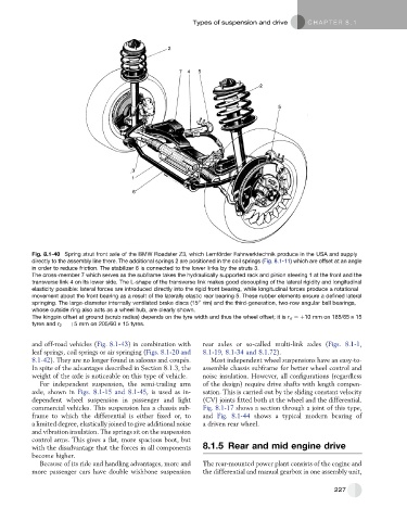
Fig. 8.1-40 Spring strut front axle of the BMW Roadster Z3, which Lemfo ¨ rder Fahrwerktechnik produce in the USA and supply
directly to the assembly line there. The additional springs 2 are positioned in the coil springs (Fig. 8.1-11) which are offset at an angle
in order to reduce friction. The stabilizer 6 is connected to the lower links by the struts 3.
The cross-member 7 which serves as the subframe takes the hydraulically supported rack and pinion steering 1 at the front and the
transverse link 4 on its lower side. The L-shape of the transverse link makes good decoupling of the lateral rigidity and longitudinal
elasticity possible: lateral forces are introduced directly into the rigid front bearing, while longitudinal forces produce a rotational
movement about the front bearing as a result of the laterally elastic rear bearing 5. These rubber elements ensure a defined lateral
00
springing. The large-diameter internally ventilated brake discs (15 rim) and the third-generation, two-row angular ball bearings,
whose outside ring also acts as a wheel hub, are clearly shown.
The kingpin offset at ground (scrub radius) depends on the tyre width and thus the wheel offset; it is r s ¼þ10 mm on 185/65 R 15
tyres and r 2 ¼þ5 mm on 205/60 R 15 tyres.
and off-road vehicles (Fig. 8.1-43) in combination with rear axles or so-called multi-link axles (Figs. 8.1-1,
leaf springs, coil springs or air springing (Figs. 8.1-20 and 8.1-19, 8.1-34 and 8.1.72).
8.1-42). They are no longer found in saloons and coupe ´s. Most independent wheel suspensions have an easy-to-
In spite of the advantages described in Section 8.1.3, the assemble chassis subframe for better wheel control and
weight of the axle is noticeable on this type of vehicle. noise insulation. However, all configurations (regardless
For independent suspension, the semi-trailing arm of the design) require drive shafts with length compen-
axle, shown in Figs. 8.1-15 and 8.1-45,isusedasin- sation. This is carried out by the sliding constant velocity
dependent wheel suspension in passenger and light (CV) joints fitted both at the wheel and the differential.
commercial vehicles. This suspension has a chassis sub- Fig. 8.1-17 shows a section through a joint of this type,
frame to which the differential is either fixed or, to and Fig. 8.1-44 shows a typical modern bearing of
a limited degree, elastically joined to give additional noise a driven rear wheel.
and vibration insulation. The springs sit on the suspension
control arms. This gives a flat, more spacious boot, but
with the disadvantage that the forces in all components 8.1.5 Rear and mid engine drive
become higher.
Because of its ride and handling advantages, more and The rear-mounted power plant consists of the engine and
more passenger cars have double wishbone suspension the differential and manual gearbox in one assembly unit,
227