
Page 215 - Automotive Engineering Powertrain Chassis System and Vehicle Body
P. 215
Types of suspension and drive CHAPTER 8.1
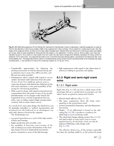
Fig. 8.1-18 Multi-link suspension of Ford Werke AG. Derived from the Mondeo Turnier model series, multi-link suspension is used by
Ford for the first time in the Focus models (1998) in the segment of C class vehicles. This is called the ‘control sword axle’ after the
shape of the longitudinal link. As there are five load paths available here, instead of the two that exist in twist-beam axles and trailing
arm axles, there is great potential for improvement with regard to the adjustment of riding comfort, driving safety and noise and
vibration insulation. As a result of a very elastic front arm bush, the high level of longitudinal flexibility necessary for riding comfort is
achieved. At the same time, very rigid and accurate wheel control for increased driving safety is ensured by the transverse link, even
at the stability limit. The longitudinal link is subject to torsional stress during wheel lift and to buckling stress when reversing. By using
moulded parts, it was possible to reduce the unsprung masses by 3.5 kg per wheel.
Considerable opportunities for balancing the high requirements with regard to the observation of
pitching movements of vehicles during braking and tolerances relating to geometry and rigidity.
acceleration (up to more than 100% anti-dive, anti-
lift and anti-squat possible).
Advantageous wheel control with regard to toe-in, 8.1.3 Rigid and semi-rigid crank
camber and track width behaviour from the point axles
of view of tyre force build-up, and tyre wear as
a function of jounce with almost free definition of the 8.1.3.1 Rigid axles
roll centre and hence a very good possibility of bal-
ancing the self-steering properties. Rigid axles (Fig. 8.1-20) can have a whole series of dis-
Wide scope for design with regard to elastokinematic advantages that are a consideration in passenger cars, but
compensation from the point of view of (a) specific which can be accepted in commercial vehicles:
elastokinematic toe-in changes under lateral and
longitudinal forces and (b) longitudinal elasticity Mutual wheel influence (Fig. 8.1-21).
with a view to riding comfort (high running wheel The space requirement above the beam corre-
comfort) with accurate wheel control.
sponding to the spring bump travel.
As a result of the more open design, the wheel forces can Limited potential for kinematic and elastokinematic
be optimally controlled, i.e. without superposition, and fine-tuning.
introduced into the bodywork in an advantageous way Weight – if the differential is located in the axle
with wide distances between the supports. casing (Fig. 8.1-20), it produces a tendency for
The disadvantages are: wheel hop to occur on bumpy roads.
The wheel load changes during traction (Fig. 8.1-22)
increased expenditure as a result of the high number
and (particularly on twin tyres) there is a poor
of links and bearings;
support base b Sp for the body, which can only be
higher production and assembly costs; improved following costly design work
the possibility of kinematic overcorrection of the (Fig. 8.1-42).
axle resulting in necessary deformation of the bear-
ings during vertical or longitudinal movements; The effective distance b Sp of the springs is generally
greater sensitivity to wear of the link bearings; less than the tracking width b r , so the projected spring
217