
Page 216 - Automotive Engineering Powertrain Chassis System and Vehicle Body
P. 216
CH AP TER 8 .1 Types of suspension and drive
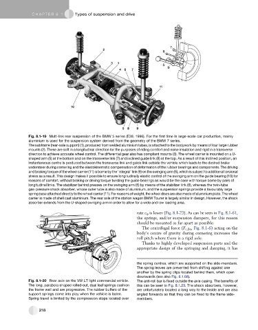
Fig. 8.1-19 Multi-link rear suspension of the BMW 5 series (E39, 1996). For the first time in large-scale car production, mainly
aluminium is used for the suspension system derived from the geometry of the BMW 7 series.
The subframe (rear-axle support) (1), produced from welded aluminium tubes, is attached to the bodywork by means of four large rubber
mounts (2). These are soft in a longitudinal direction for the purposes of riding comfort and noise insulation and rigid in a transverse
direction to achieve accurate wheel control. The differential gear also has compliant mounts (3). The wheel carrier is mounted on a U-
shaped arm (5) at the bottom and on the transverse link (7) and inclined guide link (8) at the top. As a result of this inclined position, an
instantaneous centre is produced between the transverse link and guide link outside the vehicle which leads to the desired brake
understeer during cornering and the elastokinematic compensation of deformation of the rubber bearings and components. The driving
and braking torque of the wheel carrier (11) is borne by the ‘integral’ link (9) on the swinging arm (5), which is subject to additional torsional
stress as a result. This design makes it possible to ensure longitudinally elastic control of the swinging arm on the guide bearing (10) for
reasons of comfort, without braking or driving torque twisting the guide bearings as would be the case with torque borne by pairs of
longitudinal links. The stabilizer behind presses on the swinging arm (5) by means of the stabilizer link (6), whereas the twin-tube
gas-pressure shock absorber, whose outer tube is also made of aluminium, and the suspension springs provide a favourably large
spring base attached directly to the wheel carrier (11). For reasons of weight, the wheel discs are also made of aluminium plate. The wheel
carrier is made of shell cast aluminium. The rear axle of the station wagon BMW Tourer is largely similar in design. However, the shock
absorber extends from the U-shaped swinging arm in order to allow for a wide and low loading area.
rate c 4 is lower (Fig. 8.1-23). As can be seen in Fig. 8.1-61,
the springs, and/or suspension dampers, for this reason
should be mounted as far apart as possible.
The centrifugal force (F c,Bo , Fig. 8.1-6) acting on the
body’s centre of gravity during cornering increases the
roll pitch where there is a rigid axle.
Thanks to highly developed suspension parts and the
appropriate design of the springing and damping, it has
the spring centres, which are supported on the side-members.
The spring leaves are prevented from shifting against one
another by the spring clips located behind them, which open
downwards (see also Fig. 8.1.68).
Fig. 8.1-20 Rear axle on the VW LT light commercial vehicle. The anti-roll bar is fixed outside the axle casing. The benefits of
The long, parabola-shaped rolled-out, dual leaf springs cushion this can be seen in Fig. 8.1.23. The shock absorbers, however,
the frame well and are progressive. The rubber buffers of the are unfortunately located a long way to the inside and are also
support springs come into play when the vehicle is laden. angled forwards so that they can be fixed to the frame side-
Spring travel is limited by the compression stops located over members.
218