
Page 217 - Automotive Engineering Powertrain Chassis System and Vehicle Body
P. 217
Types of suspension and drive CHAPTER 8.1
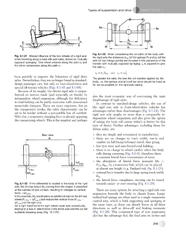
Fig. 8.1-23 When considering the roll pitch of the body with
Fig. 8.1.21 Mutual influence of the two wheels of a rigid axle the rigid axle the distances b Sp (of the springs F) and b S (of the
when travelling along a road with pot-holes, shown as ‘mutually
anti-roll bar linkage points) are included in the calculation of the
opposed springing’. One wheel extends along the path s 2 and transfer with mutually opposed springing. i 4 is squared to give
the other compresses along the path s 1 .
the rate c 4 :
i 4 [ b r =b Sp and c 4 [ c r i 2 4
been possible to improve the behaviour of rigid drive
axles. Nevertheless, they are no longer found in standard- The greater the ratio, the less the roll reaction applied by the
body, i.e. the springs and anti-roll bar arms should be fixed as
design passenger cars, but only on four-wheel-drive and far out as possible on the rigid axle casing.
special all-terrain vehicles (Figs. 8.1-43 and 8.1-68).
Because of its weight, the driven rigid axle is outper-
formed on uneven roads (and especially on bends) by also the most economic way of overcoming the main
independent wheel suspension, although the deficiency disadvantage of rigid axles.
in road-holding can be partly overcome with pressurized In contrast to standard-design vehicles, the use of
mono-tube dampers. These are more expensive, but on
the rigid rear axle in front-wheel-drive vehicles has
the compressive stroke, the valve characteristic can be
advantages rather than disadvantages (Fig. 8.1-24). The
set to be harder without a perceptible loss of comfort.
rigid rear axle weighs no more than a comparable in-
With this, a responsive damping force is already opposing
dependent wheel suspension and also gives the option
the compressing wheels. This is the simplest and perhaps
of raising the body roll centre (which is better for this
type of drive). Further advantages, including those for
driven axles, are:
they are simple and economical to manufacture;
there are no changes to track width, toe-in and
camber on full bump/rebound-travel, thus giving
low tyre wear and sure-footed road holding;
there is no change to wheel camber when the body
rolls during cornering (Fig. 8.1-6), therefore there
is constant lateral force transmission of tyres;
the absorption of lateral force moment M Y ¼
F T,X h Ro,r by a transverse link, which can be placed
at almost any height (e.g. Panhard rod, Fig. 8.1-25);
optimal force transfer due to large spring track width
bs p
the lateral force compliance steering can be tuned
Fig. 8.1-22 If the differential is located in the body of the rigid towards under- or over-steering (Fig. 8.1-29).
axle, the driving torque M A coming from the engine is absorbed
at the centres of tyre contact, resulting in changes to vertical There are many options for attaching a rigid axle rear
force DF y,W,r . suspension beneath the body or chassis frame. Longi-
In the example, M A would place an additional load on the left rear tudinal leaf springs are often used as a single suspension
wheel (F Y,W,r þ DF y,w,r ) and reduce the vertical force (F Y,W,r control arm, which is both supporting and springing at
DF y,w,r ) on the right one.
On a right-hand bend the right wheel could spin prematurely, the same time, as these can absorb forces in all three
leading to a loss in lateral force in the entire axle and the car tail directions as well as drive-off and braking moments
suddenly breaking away (Fig. 10.1-37). (Fig. 8.1-26). This economical type of rear suspension
also has the advantage that the load area on lorries and
219