
Page 212 - Automotive Engineering Powertrain Chassis System and Vehicle Body
P. 212
CH AP TER 8 .1 Types of suspension and drive
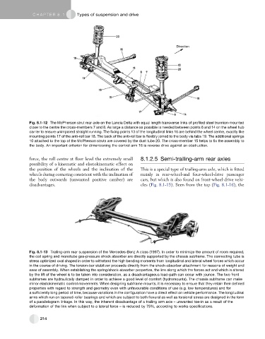
Fig. 8.1-12 The McPherson strut rear axle on the Lancia Delta with equal length transverse links of profiled steel trunnion-mounted
close to the centre the cross-members 7 and 8. As large a distance as possible is needed between points 6 and 14 on the wheel hub
carrier to ensure unimpaired straight running. The fixing points 13 of the longitudinal links 16 are behind the wheel centre, exactly like
mounting points 17 of the anti-roll bar 18. The back of the anti-roll bar is flexibly joined to the body via tabs 19. The additional springs
10 attached to the top of the McPherson struts are covered by the dust tube 20. The cross-member 15 helps to fix the assembly to
the body. An important criterion for dimensioning the control arm 16 is reverse drive against an obstruction.
force, the roll centre at floor level the extremely small 8.1.2.5 Semi-trailing-arm rear axles
possibility of a kinematic and elastokinematic effect on
the position of the wheels and the inclination of the This is a special type of trailing-arm axle, which is fitted
wheels during cornering consistent with the inclination of mainly in rear-wheel-and four-wheel-drive passenger
the body outwards (unwanted positive camber) are cars, but which is also found on front-wheel-drive vehi-
disadvantages. cles (Fig. 8.1-15). Seen from the top (Fig. 8.1-16), the
Fig. 8.1-13 Trailing-arm rear suspension of the Mercedes-Benz A class (1997). In order to minimize the amount of room required,
the coil spring and monotube gas-pressure shock absorber are directly supported by the chassis subframe. The connecting tube is
stress optimized oval shaped in order to withstand the high bending moments from longitudinal and lateral wheel forces which occur
in the course of driving. The torsion-bar stabilizer proceeds directly from the shock-absorber attachment for reasons of weight and
ease of assembly. When establishing the spring/shock-absorber properties, the line along which the forces act and which is altered
by the lift of the wheel is to be taken into consideration, as a disadvantageous load-path can occur with jounce. The two front
subframes are hydraulically damped in order to achieve a good level of comfort (hydromounts). The chassis subframe can make
minor elastokinematic control movements. When designing subframe mounts, it is necessary to ensure that they retain their defined
properties with regard to strength and geometry even with unfavourable conditions of use (e.g. low temperatures) and for
a sufficiently long period of time, because variations in the configuration have a direct effect on vehicle performance. The longitudinal
arms which run on tapered-roller bearings and which are subject to both flexural as well as torsional stress are designed in the form
of a parallelogram linkage. In this way, the inherent disadvantage of a trailing arm axle – unwanted toe-in as a result of the
deformation of the link when subject to a lateral force – is reduced by 75%, according to works specifications.
214