
Page 208 - Automotive Engineering Powertrain Chassis System and Vehicle Body
P. 208
CH AP TER 8 .1 Types of suspension and drive
counteracts the change of camber caused by the roll
pitch of the body (Fig. 8.1-6). The vehicle pitch pole O
is located behind the wheels on the front axle and in
front of the wheels on the rear axle. If O r can be located
over the wheel centre, it produces not only a better anti-
dive mechanism, but also reduces the squat on the
driven rear axles (or lift on the front axles). These are
also the reasons why the double wishbone suspension is
used as the rear axle on more and more passenger cars,
irrespective of the type of drive, and why it is pro-
gressively replacing the semi-trailing link axle (Figs. 8.1-1,
8.1-62 and 8.1-77).
Fig. 8.1-6 If the body inclines by the angle 4 during cornering, 8.1.2.3 McPherson struts and strut
the outer independently suspended wheel takes on a positive
camber 3 W,o and the inner wheel takes on a negative camber dampers
3 w,i . The ability of the tyres to transfer the lateral forces F Y , W , f , o
or F Y,W,f,i decreases causing a greater required slip angle The McPherson strut is a further development of double
Equation 10.1.16, m Bo , f is the proportion of the weight of the wishbone suspension. The upper transverse link is
body over the front axle and F c,Bo,f the centrifugal force acting replaced by a pivot point on the wheel house panel,
at the level of the centre of gravity Bo. One wheel rebounds which takes the end of the piston rod and the coil spring.
and the other bumps, i.e. this vehicle has ‘reciprocal springing’,
that is: Forces from all directions are concentrated at this point
and these cause bending stress in the piston rod. To avoid
detrimental elastic camber and caster changes, the
F Z;W;f;o ¼ F Z;W;f D DF Z;W;f
normal rod diameter of 11 mm (in the shock absorber)
F Z;W;f;i ¼ F Z;W;f L DF Z;W;f
must be increased to at least 18 mm. With a piston
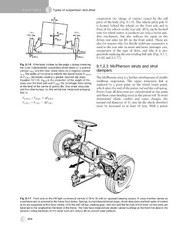
Fig. 8.1-7 Front axle on the VW light commercial vehicle Lt 28 to 35 with an opposed steering square. A cross-member serves as
a subframe and is screwed to the frame from below. Springs, bump/rebound-travel stops, shock absorbers and both pairs of control
arms are supported at this force centre. Only the anti-roll bar, steering gear, idler arm and the tie-rods of the lower control arms are
fastened to the longitudinal members of the frame. The rods have longitudinally elastic rubber bushings at the front that absorb the
dynamic rolling hardness of the radial tyres and reduce lift on uneven road surfaces.
210