
Page 205 - Automotive Engineering Powertrain Chassis System and Vehicle Body
P. 205
Types of suspension and drive CHAPTER 8.1
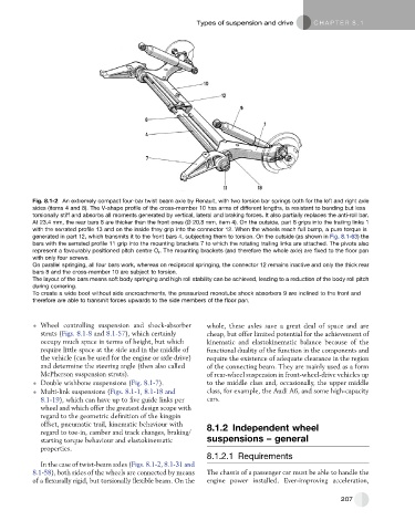
Fig. 8.1-2 An extremely compact four-bar twist beam axle by Renault, with two torsion bar springs both for the left and right axle
sides (items 4 and 8). The V-shape profile of the cross-member 10 has arms of different lengths, is resistant to bending but less
torsionally stiff and absorbs all moments generated by vertical, lateral and braking forces. It also partially replaces the anti-roll bar.
At 23.4 mm, the rear bars 8 are thicker than the front ones (Ø 20.8 mm, item 4). On the outside, part 8 grips into the trailing links 1
with the serrated profile 13 and on the inside they grip into the connector 12. When the wheels reach full bump, a pure torque is
generated in part 12, which transmits it to the front bars 4, subjecting them to torsion. On the outside (as shown in Fig. 8.1-63) the
bars with the serrated profile 11 grip into the mounting brackets 7 to which the rotating trailing links are attached. The pivots also
represent a favourably positioned pitch centre O r . The mounting brackets (and therefore the whole axle) are fixed to the floor pan
with only four screws.
On parallel springing, all four bars work, whereas on reciprocal springing, the connector 12 remains inactive and only the thick rear
bars 8 and the cross-member 10 are subject to torsion.
The layout of the bars means soft body springing and high roll stability can be achieved, leading to a reduction of the body roll pitch
during cornering.
To create a wide boot without side encroachments, the pressurized monotube shock absorbers 9 are inclined to the front and
therefore are able to transmit forces upwards to the side members of the floor pan.
Wheel controlling suspension and shock-absorber whole, these axles save a great deal of space and are
struts (Figs. 8.1-8 and 8.1-57), which certainly cheap, but offer limited potential for the achievement of
occupy much space in terms of height, but which kinematic and elastokinematic balance because of the
require little space at the side and in the middle of functional duality of the function in the components and
the vehicle (can be used for the engine or axle drive) require the existence of adequate clearance in the region
and determine the steering angle (then also called of the connecting beam. They are mainly used as a form
McPherson suspension struts). of rear-wheel suspension in front-wheel-drive vehicles up
Double wishbone suspensions (Fig. 8.1-7). to the middle class and, occasionally, the upper middle
Multi-link suspensions (Figs. 8.1-1, 8.1-18 and class, for example, the Audi A6, and some high-capacity
8.1-19), which can have up to five guide links per cars.
wheel and which offer the greatest design scope with
regard to the geometric definition of the kingpin
offset, pneumatic trail, kinematic behaviour with 8.1.2 Independent wheel
regard to toe-in, camber and track changes, braking/
starting torque behaviour and elastokinematic suspensions – general
properties.
8.1.2.1 Requirements
In the case of twist-beam axles (Figs. 8.1-2, 8.1-31 and
8.1-58), both sides of the wheels are connected by means The chassis of a passenger car must be able to handle the
of a flexurally rigid, but torsionally flexible beam. On the engine power installed. Ever-improving acceleration,
207