
Page 206 - Automotive Engineering Powertrain Chassis System and Vehicle Body
P. 206
CH AP TER 8 .1 Types of suspension and drive
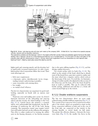
Fig. 8.1-3 Driven, rigid steering axle with dual joint made by the company GKN – Birfield AG for four-wheel-drive special-purpose
vehicles, tractors and construction machinery.
The dual joint is centred over the bearings 1 and 2 in the region of the fork carriers; these are protected against fouling by the radial
sealing rings 3. Bearing 1 serves as a fixed bearing and bearing 2 as a movable bearing. The drive shaft 4 is also a sun gear for the
planetary gear with the internal-geared wheel 5. Vertical, lateral and longitudinal forces are transmitted by both tapered-roller
bearings 6 and 7. Steering takes place about the steering axis EG.
higher peak and cornering speeds, and deceleration lead due to the parts rubbing together (Fig. 8.1-11), and the
to significantly increased requirements for safer chassis. driving comfort decreases.
Independent wheel suspensions follow this trend. Their The wheels incline with the body (Fig. 8.1-6). The
main advantages are: wheel on the outside of the bend, which has to absorb
most of the lateral force, goes into a positive camber and
little space requirement; the inner wheel into a negative camber, which reduces
a kinematic and/or elastokinematic toe-in change, the lateral grip of the tyres. To avoid this, the kinematic
tending towards understeering is possible; change of camber needs to be adjusted to take account of
easier steerability with existing drive; this behaviour and the body roll in the bend should be
low weight; kept as small as possible. This can be achieved with
no mutual wheel influence. harder springs, additional anti-roll bars or a body roll
centre located high up in the vehicle.
The last two characteristics are important for good road-
holding, especially on bends with an uneven road
surface. 8.1.2.2 Double wishbone suspensions
Transverse arms and trailing arms ensure the desired
kinematic behaviour of the rebounding and jouncing The last two characteristics above are most easily
wheels and also transfer the wheel loadings to the body achieved using a double wishbone suspension (Fig. 8.1-7).
(Fig. 8.1-5). Lateral forces also generate a moment This consists of two transverse links (control arms) either
which, with unfavourable link arrangement, has the dis- side of the vehicle, which are mounted to rotate on the
advantage of reinforcing the roll of the body during frame, suspension subframe or body and, in the case of
cornering. The suspension control arms require bushes the front axle, are connected on the outside to the
that yield under load and can also influence the springing. steering knuckle or swivel heads via ball joints.
This effect is either reinforced by twisting the rubber The greater the effective distance c between the trans-
parts in the bearing elements, or the friction increases verse links (Fig. 8.1-5), the smaller the forces in the
208