
Page 207 - Automotive Engineering Powertrain Chassis System and Vehicle Body
P. 207
Types of suspension and drive CHAPTER 8.1
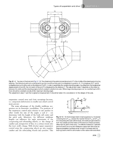
Fig. 8.1-4 Top view of the dual joint (Fig. 8.1-3). The wheel end of the axle is turned about point P in the middle of the steering pivot during
0
0
steering. The individual joints are constrained at points A and B so that point A is displaced to position A , P is displaced to P and B
0
is displaced along the drive axle by the distance X to B . In order to assimilate the variable bending angle b resulting from the longitudinal
displacement of point B, the mid-point of the joint P is displaced by the distance Y. The adjustment value Y depends on the distance
between the joints and the steering angle at which constant velocity is to exist. Where large steering angles can be reached (up to 60 ),
there should be constant velocity at the maximum steering angle.
The adjustment value Y and the longitudinal displacement X should be taken into consideration in the design of the axle.
suspension control arms and their mountings become,
i.e. component deformation is smaller and wheel control
more precise.
The main advantages of the double wishbone sus-
pension are its kinematic possibilities. The positions of
the suspension control arms relative to one another–in
other words the size of the angles a and b – can
determine both the height of the body roll centre and
the pitch pole. Moreover, the different wishbone Fig. 8.1-5 On front independent wheel suspensions, the lateral
lengths can influence the angle movements of the cornering force F Y , W , f causes the reaction forces F Y , E and F Y , G in
the links joining the axle with the body. Moments are generated on
compressing and rebounding wheels, i.e. the change of
camber and, irrespective of this, to a certain extent also both the outside and the inside of the bend and these adversely
affect the roll pitch of the body. The effective distance c between
the track width change. With shorter upper suspension points E and G on a double wishbone suspension should be as
control arms the compressing wheels go into negative large as possible to achieve small forces in the body and link
camber and the rebounding wheels into positive. This bearings and to limit the deformation of the rubber elements fitted.
209