
Page 231 - Automotive Engineering Powertrain Chassis System and Vehicle Body
P. 231
Types of suspension and drive CHAPTER 8.1
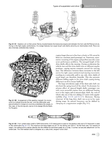
Fig. 8.1-51 Gearbox unit on the Lancia Thema, located beside the transverse engine and between the front axle McPherson struts.
Owing to the high engine performance, the design features two equal-length axle shafts joined by an intermediate shaft. There are
also internally ventilated disc brakes.
engines larger than an in-line four cylinder or V6 cannot be
fitted in a medium-sized passenger car. Transverse, asym-
metric mounting of the engine and gearbox may also cause
some performance problems. The unequal length of the
drive shafts affects the steering. During acceleration the
vehicle rises and the drive shafts take on different angular
positions, causing uneven moments around the steering
axes. The difference between these moments to the left
and to the right causes unintentional steering movements
resulting in a noticeable pull to one side; drive shafts of
equal length are therefore desirable. This also prevents
different drilling angles in the drive shaft causing timing
differences in drive torque build-up.
The large articulation angle of the short axle shaft can
also limit the spring travel of the wheel. To eliminate the
adverse effect of unequal length shafts, passenger cars
with more powerful engines have an additional bearing
next to the engine and an intermediate shaft, the ends of
which take one of the two sliding CV joints with angular
mobility (Figs. 8.1-51 and 8.1-17). Moreover, ’flexing
vibration’ of the long drive shaft can occur in the main
Fig. 8.1-52 Arrangement of the gearbox beneath the motor, driving range. Its natural frequency can be shifted by
which is inclined towards the rear, and the differential gear
placed behind it. A single oil-economy undertakes the supply, in clamping on a suppression weight (Fig. 9.1).
this case, of the driving unit, narrow in its design (Works Illustr.
Fa Peugeot).
Fig. 8.1-53 Front-wheel output shaft of GKN Automotive. A CV sliding joint is used on the gearbox side and a CV fixed joint is used
on the wheel side (Fig. 8.1-17). The maximum bending angles are 22 for the sliding joint and 47 for the fixed joint. For reasons of
weight, the sliding joint is placed directly into the differential and fixed axially by a circlip. A central nut secures attachment on the
wheel side. The intermediate shaft is designed as a carburized, shaped hollow shaft.
233