
Page 235 - Automotive Engineering Powertrain Chassis System and Vehicle Body
P. 235
Types of suspension and drive CHAPTER 8.1
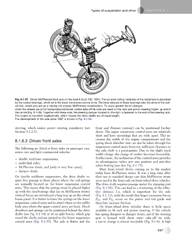
Fig. 8.1-57 Driven McPherson front axle on the Audi 6 (Audi 100, 1991). The dynamic rolling hardness of the radial tyre is absorbed
by the rubber bearings, which sit in the lower transverse control arms. The inner sleeves of these bearings take the arms of the anti-
roll bar, which also act as a trailing link (classic McPherson construction). To avoid greater toe-in changes
when the wheels are at full bump/rebound-travel, centre take-off tie rods are used on the rack and pinion steering higher up and in
the centre (Fig. 9.1-39). Together with these rods, the steering damper located on the right is fastened to the end of the steering rack.
The engine is mounted longitudinally, which means the drive shafts are of equal length.
The development of the axle since 1997 is shown in Fig. 8.1-54.
steering, which makes power steering mandatory (see front end (bonnet contour) can be positioned further
Section 9.1.2.5). down. The upper suspension control arms are relatively
short and have mountings that are wide apart. This in-
creases the width of the engine compartment and the
8.1.6.3 Driven front axles
spring shock absorber unit can also be taken through the
suspension control arms; however, sufficient clearance to
The following are fitted as front axles on passenger cars,
estate cars and light commercial vehicles: the axle shaft is a prerequisite. Due to the slight track
width change, the change of camber becomes favourable.
double wishbone suspensions; Furthermore, the inclination of the control arms provides
multi-link axles; an advantageous radius arm axis position and anti-dive
McPherson struts, and (only in very few cases); when braking (see also Fig. 8.1-75).
Most front-wheel drives coming on to the market
damper struts.
today have McPherson struts. It was a long time after
On double wishbone suspensions, the drive shafts re- their use in standard design cars that McPherson struts
quire free passage in those places where the coil springs were used at the front axle on front-wheel drive vehicles.
are normally located on the lower suspension control The drive shaft requires passage under the damping part
arms. This means that the springs must be placed higher (Fig. 8.1-56). This can lead to a shortening of the effec-
up with the disadvantage that (as on McPherson struts) tive distance l–o, which is important for the axle
vertical forces are introduced a long way up on the wheel (Fig. 8.1-11), with the result that larger transverse forces
house panel. It is better to leave the springs on the lower F Y,C and F Y , K occur on the piston and rod guide and
suspension control arms and to attach these to the stiffer therefore increase friction.
body area where the upper control arms are fixed. Shock On front-wheel-drive vehicles there is little space
absorbers and springs can be positioned behind the drive available to fit rack and pinion steering. If the vehicle
shafts (see Fig. 8.1-54) or sit on split braces, which grip has spring dampers or damper struts, and if the steering
round the shafts and are jointed to the lower suspension gear is housed with short outer take-off tie rods,
control arms (Fig. 8.1-55). The axle is flatter and the a toe-in change is almost inevitable (Fig. 9.1-4). A high
237