
Page 238 - Automotive Engineering Powertrain Chassis System and Vehicle Body
P. 238
CH AP TER 8 .1 Types of suspension and drive
non-variable track and camber values during drive.
Fig. 8.1-24 illustrates an inexpensive yet effective design:
axle casing in steel tubing;
suspension on single leaf springs.
The lateral and longitudinal wheel control character-
istics are sufficient for passenger cars in the medium
to small vehicle range and delivery vehicles. The re-
sultant hard springing is acceptable and may even be
necessary because of the load to be moved. The wheel
bearing can be simple on such axles (Fig. 8.1-59).
Faster, more comfortable vehicles, on the other hand,
require coil springs and, for precise axle control,
trailing links and a good central guide (Fig. 8.1-60)or
Panhard rod. This is generally positioned behind the
axle (Fig. 8.1-61).
8.1.6.4.3 Independent wheel suspension
An independent wheel suspension is not necessarily
better than a rigid axle in terms of handling proper-
ties. The wheels may incline with the body and the
lateral grip characteristics of the tyres decrease, and
there are hardly any advantages in terms of weight.
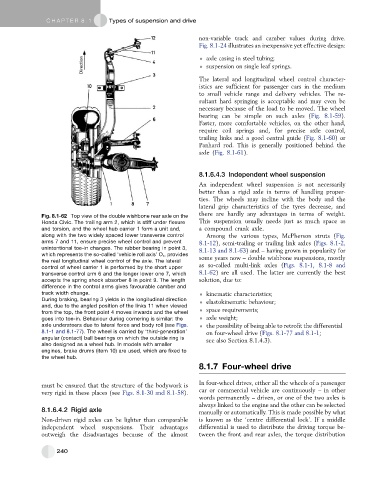
Fig. 8.1-62 Top view of the double wishbone rear axle on the
Honda Civic. The trailing arm 2, which is stiff under flexure This suspension usually needs just as much space as
and torsion, and the wheel hub carrier 1 form a unit and, a compound crank axle.
along with the two widely spaced lower transverse control Among the various types, McPherson struts (Fig.
arms 7 and 11, ensure precise wheel control and prevent 8.1-12), semi-trailing or trailing link axles (Figs. 8.1-2,
unintentional toe-in changes. The rubber bearing in point 3, 8.1-13 and 8.1-63) and – having grown in popularity for
which represents the so-called ‘vehicle roll axis’ O r ,provides
some years now – double wishbone suspensions, mostly
the real longitudinal wheel control of the axle. The lateral
control of wheel carrier 1 is performed by the short upper as so-called multi-link axles (Figs. 8.1-1, 8.1-8 and
transverse control arm 6 and the longer lower one 7, which 8.1-62) are all used. The latter are currently the best
accepts the spring shock absorber 8 in point 9. The length solution, due to:
difference in the control arms gives favourable camber and
track width change. kinematic characteristics;
During braking, bearing 3 yields in the longitudinal direction elastokinematic behaviour;
and, due to the angled position of the links 11 when viewed
from the top, the front point 4 moves inwards and the wheel space requirements;
goes into toe-in. Behaviour during cornering is similar: the axle weight;
axle understeers due to lateral force and body roll (see Figs. the possibility of being able to retrofit the differential
8.1-1 and 8.1-77). The wheel is carried by ‘third-generation’ on four-wheel drive (Figs. 8.1-77 and 8.1-1;
angular (contact) ball bearings on which the outside ring is see also Section 8.1.4.3).
also designed as a wheel hub. In models with smaller
engines, brake drums (item 10) are used, which are fixed to
the wheel hub.
8.1.7 Four-wheel drive
must be ensured that the structure of the bodywork is In four-wheel drives, either all the wheels of a passenger
very rigid in these places (see Figs. 8.1-30 and 8.1-58). car or commercial vehicle are continuously – in other
words permanently – driven, or one of the two axles is
always linked to the engine and the other can be selected
8.1.6.4.2 Rigid axle manually or automatically. This is made possible by what
Non-driven rigid axles can be lighter than comparable is known as the ‘centre differential lock’. If a middle
independent wheel suspensions. Their advantages differential is used to distribute the driving torque be-
outweigh the disadvantages because of the almost tween the front and rear axles, the torque distribution
240