
Page 239 - Automotive Engineering Powertrain Chassis System and Vehicle Body
P. 239
Types of suspension and drive CHAPTER 8.1
Fig. 8.1-63 Compact trailing arm rear axle, fitted by Renault to less powerful medium-sized vehicles. The short torsion bar springs
grip into the guide tubes 2 and 3 in the centre of the vehicle. Parts 2, 3 and 4 are jointly subjected to torsional stresses and so the
torsional stiffness of the transverse tubes contributes to the spring rate. On the outside, the cast trailing arms 1 are welded to the
transverse tubes, which (pushed into each other) support each other on the torsionally elastic bearings 5 and 6. This creates
a sufficiently long bearing basis, which largely prevents camber and toe-in changes when forces are generated.
The entire assembly is fixed by the brackets 7 which permits better force transfer on the body side sill. Guide tubes 2 and 3 are
mounted in the brackets and can rotate, as well as the outer sides of the two torsion bars 4. The two arms thus transfer all vertical
forces plus the entire springing moment to the body. The anti-roll bar 8 is connected to the two trailing arms via two U-shaped tabs.
The two rubber bearings 5 and 6 located between the tubes 2 and 3 also contribute to the stabilizing effect.
The bump and rebound travel stops are fitted into the shock absorber 9. As shown in Fig. 8.1-2, on the newer models, the dampers
would be inclined so that they can be fixed to the side members of the floor pan which also leads to more space between the wheel
housings.
7.2
can be established on the basis of the axle–load ratios, the
6.4 design philosophy of the vehicle and the desired handling
characteristics. That is why Audi choose a 50%:50%
4-wheel drive with winter tyres
5.6 distribution for the V8 Quattro and Mercedes-Benz
choose a 50%:50% distribution for M class off-road ve-
4.8 hicles, whereas Mercedes-Benz transmits only 35% of
the torque to the front axle and as much as 65% to the
4.0 rear axle in vehicles belonging to the E class.
Traction force kN 3.2 Front-wheel drive with winter tyres drive designs. In spite of the advantages of four-wheel
This section deals with the most current four-wheel-
drive, suitable tyres – as shown in Fig. 8.1-64 – should be
2.4
1.6 4-wheel drive with summer tyres fitted in winter.
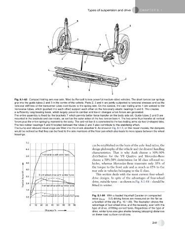
Front-wheel drive with summer tyres Fig. 8.1-64 With a loaded Vauxhall Cavalier on compacted
0.8
snow (m X,W ¼ 0.2) driving forces are measured on the flat as
a function of the slip (Fig. 10.1-33). The illustration shows the
0 10 20 30 40 50 60 70 80 advantage of four-wheel drive, and the necessity, even with this
type of drive, of fitting correct tyres. Regardless of the type of
Slippage %
drive, winter tyres also give shorter braking (stopping) distances
on these road surface conditions.
241