
Page 237 - Automotive Engineering Powertrain Chassis System and Vehicle Body
P. 237
Types of suspension and drive CHAPTER 8.1
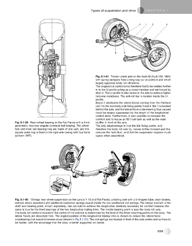
Fig. 8.1-61 Torsion crank axle on the Audi A6 (Audi 100, 1991)
with spring dampers fixed a long way out at points 6 and which
largely suppress body roll vibrations.
The longitudinal control arms therefore had to be welded further
in to the U-profile acting as a cross-member and reinforced by
shoe 5. The U-profile is also raised at the side to achieve higher
torsional resistance. The anti-roll bar is located inside the U-
profile.
Brace 2 distributes the lateral forces coming from the Panhard
rod 1 to the two body-side fixing points 3 and 4. Bar 1 is located
behind the axle, and the lateral force understeering thus caused
could be largely suppressed by the length of the longitudinal
control arms. Furthermore, it was possible to increase the
comfort and to house an 80 l fuel tank as well as the main
Fig. 8.1-59 Rear+wheel bearing on the Fiat Panda with a third- muffler in front of the axle.
generation, two-row angular (contact) ball bearing. The wheel The only disadvantage is that the link fixing points, and
hub and inner ball bearing ring are made of one part, and the therefore the body roll axis O r , moves further forward and this
square outer ring is fixed to the rigid axle casing with four bolts reduces the ‘anti-dive’, and that the suspension requires much
(picture: SKF). space when assembled.
Fig. 8.1-60 ’Omega’ rear wheel suspension on the Lancia Y 10 and Fiat Panda, a trailing axle with a U-shaped tube, drum brakes,
inclined shock absorbers and additional elastomer springs seated inside the low-positioned coil springs. The rubber element in the
shaft axle bearing point, shown separately, has cut-outs to achieve the longitudinal elasticity necessary for comfort reasons; the
same is true for the front bearings of the two longitudinal trailing links. The middle bearing point is also the body roll axis.
The body roll centre is located in the centre of the axle but is determined by the level of the three mounting points on the body. The
lateral forces are absorbed here. The angled position of the longitudinal trailing links is chosen to reduce the lateral force
oversteering that would otherwise occur (shown in Fig 8.1-31). The coil springs are located in front of the axle centre and so have to
be harder, with the advantage that the body is better supported on bends.
239