
Page 236 - Automotive Engineering Powertrain Chassis System and Vehicle Body
P. 236
CH AP TER 8 .1 Types of suspension and drive
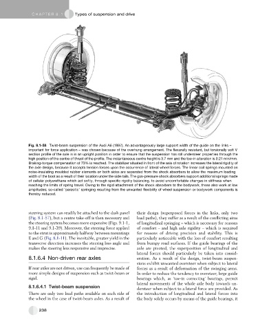
Fig. 8.1-58 Twist-beam suspension of the Audi A6 (1997). An advantageously large support width of the guide on the links –
important for force application – was chosen because of the overhung arrangement. The flexurally resistant, but torsionally soft V
section profile of the axle is in an upright position in order to ensure that the suspension has roll understeer properties through the
high position of the centre of thrust of the profile. The instantaneous centre height is 3.7 mm and the toe-in alteration is 0.21 min/mm.
Braking-torque compensation of 73% is reached. The stabilizer situated in front of the axis of rotation increases the lateral rigidity of
the axle design, because it accepts tension forces upon the occurrence of lateral wheel forces. The linear coil springs mounted on
noise-insulating moulded rubber elements on both sides are separated from the shock absorbers to allow the maximum loading
width of the boot as a result of their location under the side rails. The gas-pressure shock absorbers support additional springs made
of cellular polyurethane which act softly, through specific rigidity balancing, to avoid uncomfortable changes in stiffness when
reaching the limits of spring travel. Owing to the rigid attachment of the shock absorbers to the bodywork, these also work at low
amplitudes; so-called ‘parasitic’ springing resulting from the unwanted flexibility of wheel suspension or bodywork components is
thereby reduced.
steering system can readily be attached to the dash panel their design (superposed forces in the links, only two
(Fig. 8.1-57), but a centre take-off is then necessary and load paths), they suffer as a result of the conflicting aims
the steering system becomes more expensive (Figs. 9.1-1, of longitudinal springing – which is necessary for reasons
9.1-11 and 9.1-39). Moreover, the steering force applied of comfort – and high axle rigidity – which is required
to the strut is approximately halfway between mountings for reasons of driving precision and stability. This is
E and G (Fig. 8.1-11). The inevitable, greater yield in the particularly noticeable with the loss of comfort resulting
transverse direction increases the steering loss angle and from bumpy road surfaces. If the guide bearings of the
makes the steering less responsive and imprecise. axle are pivoted, the superposition of longitudinal and
lateral forces should particularly be taken into consid-
8.1.6.4 Non-driven rear axles eration. As a result of the design, twist-beam suspen-
sions exhibit unwanted oversteer when subject to lateral
If rear axles are not driven, use can frequently be made of forces as a result of deformation of the swinging arms.
more simple designs of suspension such as twist-beam or In order to reduce the tendency to oversteer, large guide
rigid. bearings which, as ‘toe-in correcting’ bearings, permit
lateral movements of the whole axle body towards un-
8.1.6.4.1 Twist-beam suspension dersteer when subject to a lateral force are provided. As
There are only two load paths available on each side of the introduction of longitudinal and lateral forces into
the wheel in the case of twist-beam axles. As a result of the body solely occurs by means of the guide bearings, it
238