
Page 232 - Automotive Engineering Powertrain Chassis System and Vehicle Body
P. 232
CH AP TER 8 .1 Types of suspension and drive
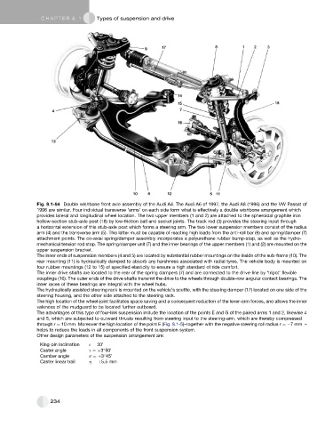
Fig. 8.1-54 Double wishbone front axle assembly of the Audi A4. The Audi A6 of 1997, the Audi A8 (1996) and the VW Passat of
1996 are similar. Four individual transverse ‘arms’ on each side form what is effectively a double wishbone arrangement which
provides lateral and longitudinal wheel location. The two upper members (1 and 2) are attached to the spheroidal graphite iron
hollow-section stub-axle post (18) by low-friction ball and socket joints. The track rod (3) provides the steering input through
a horizontal extension of this stub-axle post which forms a steering arm. The two lower suspension members consist of the radius
arm (4) and the transverse arm (5). This latter must be capable of reacting high loads from the anti-roll bar (6) and spring/damper (7)
attachment points. The co-axial spring/damper assembly incorporates a polyurethane rubber bump-stop, as well as the hydro-
mechanical tension rod stop. The spring/damper unit (7) and the inner bearings of the upper members (1) and (2) are mounted on the
upper suspension bracket.
The inner ends of suspension members (4 and 5) are located by substantial rubber mountings on the inside of the sub-frame (10). The
rear mounting (11) is hydraulically damped to absorb any harshness associated with radial tyres. The vehicle body is mounted on
four rubber mountings (12 to 15) of specified elasticity to ensure a high standard of ride comfort.
The inner drive shafts are located to the rear of the spring dampers (7) and are connected to the drive-line by ‘tripot’ flexible
couplings (16). The outer ends of the drive shafts transmit the drive to the wheels through double-row angular contact bearings. The
inner races of these bearings are integral with the wheel hubs.
The hydraulically assisted steering rack is mounted on the vehicle’s scuttle, with the steering damper (17) located on one side of the
steering housing, and the other side attached to the steering rack.
The high location of the wheel-joint facilitates space saving and a consequent reduction of the lever-arm forces, and allows the inner
valences of the mudguard to be located further outboard.
The advantages of this type of four-link suspension include the location of the points E and G of the paired arms 1 and 2, likewise 4
and 5, which are subjected to outward thrusts resulting from steering input to the steering-arm, which are thereby compressed
through r ¼ 10 mm. Moreover the high location of the point E (Fig. 8.1-5)–together with the negative steering roll radius r ¼ 7mm –
helps to reduce the loads in all components of the front suspension system.
Other design parameters of the suspension arrangement are:
King-pin inclination 3 ¼ 30 0
Caster angle s ¼þ3 50 0
Camber angle s ¼þ3 45 0
Caster linear trail h ¼þ5.5 mm
234