
Page 260 - Automotive Engineering Powertrain Chassis System and Vehicle Body
P. 260
CH AP TER 9 .1 Steering
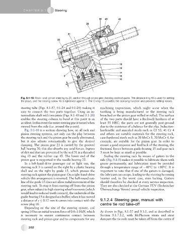
Fig. 9.1-10 Rack- and- pinion steering by ZF; section through pinion gear, bearing and rod guide. The distance ring 18 is used for setting
the plays, and the closing screw 16 is tightened against it. The O-ring 19 provides the damping function and prevents rattling noises.
steering tube (Figs. 8.1-57, 9.1-24 and 9.1-29) making it machining imprecision, which might occur when the
easy to connect the two parts together. Using an in- toothing is being manufactured or the steering rack
termediate shaft with two joints (Figs. 8.1-49 and 9.1-26) broached or the pinion gear milled or rolled. The surface
enables the steering column to bend at this point in an of the two parts should have a Rockwell hardness of at
accident.Inthiseventtheentiresteeringgearisturnedwhen least 55 HRC; the parts are not generally post-ground
viewed from the side (i.e. around the y-axis). due to the existence of a balance for the play. Induction-
Fig. 9.1-10 is a section showing how, on all rack and hardenable and annealed steels such as Cf 53, 41 Cr 4
pinion steering systems, not only can the play between and others are suitable materials for the steering rack,
the steering rack and the pinion gear be easily eliminated, case-hardened steels such as 20 MnCr 5, 20 MoCr 4, for
but it also adjusts automatically to give the desired example, are suitable for the pinion gear. In order to
damping. The pinion gear 21 is carried by the grooved ensure a good response and feedback of the steering, the
ball bearing 20; this also absorbs any axial forces. Ingress frictional forces between guide-bearing 15 and gear rack
of dirt and dust are prevented by the seal 31 in a threaded 3 must be kept as small as possible.
ring 43 and the rubber cap 45. The lower end of the Sealing the steering rack by means of gaiters to the
pinion gear is supported in the needle bearing 23. side (Fig. 9.1-9) makes it possible to lubricate them with
In a left-hand-drive passenger car or light van, the grease permanently, and lubrication must be provided
steering rack 3 is carried on the right by a plastic bearing through a temperature range of 40 Cto þ80 C. It is
shell and on the right by guide 15, which presses the important to note that if one of the gaiters is damaged,
steering rack against the pinion gear. On a right-hand-drive the lubricant can escape, leading to the steering becoming
vehicle this arrangement is reversed. The half-round out- heavier and, in the worst case, even locking. Gaiters
line of the guide 15 does not allow radial movement of the should therefore be checked at every service inspection.
¨
steering rack. To stop it from moving off from the pinion They are also checked at the German TUV (Technischer
¨
gear, when subject to high steering wheel moments (which Uberwachungs Verein) annual vehicle inspection.
would lead to reduced tooth contact), the underside of the
guide-bearing 15 is designed as a buffer; when it has moved
a distance of s 0.12 mm it comes into contact with the 9.1.2.4 Steering gear, manual with
screw plug 16. centre tie rod take-off
Depending on the size of the steering system, coil
spring 14 has an initial tension force of 0.6–1.0 kN, which As shown in Figs. 8.1-57 and 9.1-1, and as described in
is necessary to ensure continuous contact between Section 9.1.7.3.2, with McPherson struts and strut
steering rack and pinion gear and to compensate for any dampers the tie rods must be taken off from the centre if
262