
Page 262 - Automotive Engineering Powertrain Chassis System and Vehicle Body
P. 262
CH AP TER 9 .1 Steering
Fig. 9.1-12 Top view of the strut damper front axle on a Mercedes vehicle. The intermediate rod and the tie rods are fixed side by side on the
pitman and idler arms and one grips from the top and the other from the bottom into the two levers; the steering square is opposed. The
steering damper is supported on the one side at the intermediate rod and on the other side on the suspension subframe.
The anti-roll bar is linked to the lower wishbone type control arms whose inner bearings take large rubber bushings. The defined springing
stiffness of these bearings, together with the inclined position of the tie rods (when viewed from the top) means that when the vehicle corners,
there is a reduction in the steering input, i.e. elastic compliance in the steering, tending towards understeering. The strut dampers are screwed
to the steering knuckles; the negative kingpin offset is r s ¼ –14 mm.
also require the idler arm 5 (see Fig. 9.1-3) and a further This results in only low load to the pitman and inter-
intermediate rod, position 6, to connect them to the mediate arms in the event of tie rod diagonal forces
pitman arm 4; the tie rods are adjustable and have pre-lubri- occurring.
cated ball joints on both sides (Figs. 9.1-13 and 9.1-14). It is also possible to design tie rods of any length
This type of steering system is more complicated on desired, and to have steering kinematics that allow
the whole in passenger cars with independently sus- an increase in the overall steering ratio i S with increase
pended front wheels and is therefore more expensive ing steering angles. The operating forces necessary to
than rack and pinion steering systems; however, it park the vehicle are reduced in such cases.
sometimes has greater steering elasticity, which reduces
the responsiveness and steering feel in the on-centre
range. 9.1.3.2 Steering gear
Comparing the two types of configuration (without
power-assisted steering) indicates a series of advantages: The input screw shaft 4 (Fig. 9.1-15) has a round thread
in which ball bearings run, which carry the steering nut 5
Can be used on rigid axles (Figs. 9.1-5 and 8.1-37).
with them when the steering wheel is rotated. The balls
Ability to transfer high forces. which come out of the thread at the top or the bottom
A large wheel input angle possible – the steering gear (depending on the direction of rotation) are returned
shaft has a rotation range up to 45 , which can be through the tube 6. The nut has teeth on one side which
further increased by the steering ratio. mesh with the toothed segment 7 and therefore with the
It is therefore possible to use long steering arms. steering output shaft 8. When viewed from the side, the
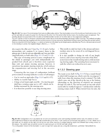
Fig. 9.1-13 Configuration of an adjustable tie rod with pre-lubricated joints and buckling-resistant central tube, the interior of which
has a right-hand thread on one side and a left-hand thread on the other. It can usually be continuously adjusted by 10 mm. When toe-in
has been set, the length on the right and left tie-rod may differ, resulting in unequal steering inputs and different size turning circles; for
this reason, the central tube should be turned the same amount on the left and right wheel.
The configuration shown in the illustration is used on rigid front axles and as a drag link (illustration: Lemfo ¨ rder Fahwerktechnik).
264