
Page 265 - Automotive Engineering Powertrain Chassis System and Vehicle Body
P. 265
Steering CHAPTER 9.1
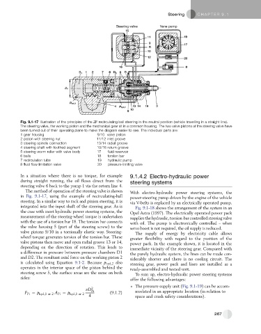
Fig. 9.1-17 Illustration of the principles of the ZF recirculating ball steering in the neutral position (vehicle travelling in a straight line).
The steering valve, the working piston and the mechanical gear sit in a common housing. The two valve pistons of the steering valve have
been turned out of their operating plane to make the diagram easier to see. The individual parts are:
1 gear housing 9/10 valve piston
2 piston with steering nut 11/12 inlet groove
3 steering spindle connection 13/14 radial groove
4 steering shaft with toothed segment 15/16 return groove
5 steering worm roller with valve body 17 fluid reservoir
6 balls 18 torsion bar
7 recirculation tube 19 hydraulic pump
8 fluid flow limitation valve 20 pressure-limiting valve
In a situation where there is no torque, for example 9.1.4.2 Electro-hydraulic power
during straight running, the oil flows direct from the steering systems
steering valve 6 back to the pump 1 via the return line 4.
The method of operation of the steering valve is shown With electro-hydraulic power steering systems, the
in Fig. 9.1-17, using the example of recirculating-ball power-steering pump driven by the engine of the vehicle
steering. In a similar way to rack and pinion steering, it is via V-belts is replaced by an electrically operated pump.
integrated into the input shaft of the steering gear. As is Fig. 9.1-18 shows the arrangement of the system in an
the case with most hydraulic power steering systems, the Opel Astra (1997). The electrically operated power pack
measurement of the steering-wheel torque is undertaken suppliesthe hydraulic,torsion-barcontrolledsteeringvalve
with the use of a torsion bar 18. The torsion bar connects with oil. The pump is electronically controlled – when
the valve housing 5 (part of the steering screw) to the servo boost is not required, the oil supply is reduced.
valve pistons 9/10 in a torsionally elastic way. Steering- The supply of energy by electricity cable allows
wheel torque generates torsion of the torsion bar. These greater flexibility with regard to the position of the
valve pistons then move and open radial groove 13 or 14, power pack. In the example shown, it is located in the
depending on the direction of rotation. This leads to immediate vicinity of the steering gear. Compared with
a difference in pressure between pressure chambers D1 the purely hydraulic system, the lines can be made con-
and D2. The resultant axial force on the working piston 2 siderably shorter and there is no cooling circuit. The
is calculated using Equation 9.1-2. Because p hyd,2 also steering gear, power pack and lines are installed as a
operates in the interior space of the piston behind the ready-assembled and tested unit.
steering screw 5, the surface areas are the same on both To sum up, electro-hydraulic power steering systems
sides: offer the following advantages:
The pressure supply unit (Fig. 9.1-19) can be accom-
pD 2
F Pi ¼ p hyd;1or2 A Pi ¼ p hyd;1or2 4 Pi (9.1.2) modated in an appropriate location (in relation to
space and crash safety considerations).
267