
Page 264 - Automotive Engineering Powertrain Chassis System and Vehicle Body
P. 264
CH AP TER 9 .1 Steering
detected by a measurement system located in the region power steering systems have to be designed in such a
of the input shaft of the steering gear or in the steering way that a sufficient supply volume is available for fast
tube, and additional forces or moments are introduced steering movements even at a low engine speed, supply
into the system. This follows a characteristic curve flow limiting valves are required. These limit the supply
(valve characteristic) or group of curves depending on flow to about 8 l per minute in order to prevent the
the height of the steering-wheel torque, if another hydraulic losses which would otherwise occur at higher
quantity, e.g. driving speed, is entered as a signal. The engine speeds. Depending on the driving assembly and
steering boost is thereby reduced, with the aim of pump design, the additional consumption of fuel can lie
achieving better road contact at higher speeds. between 0.2 and 0.7 l per 100 km.
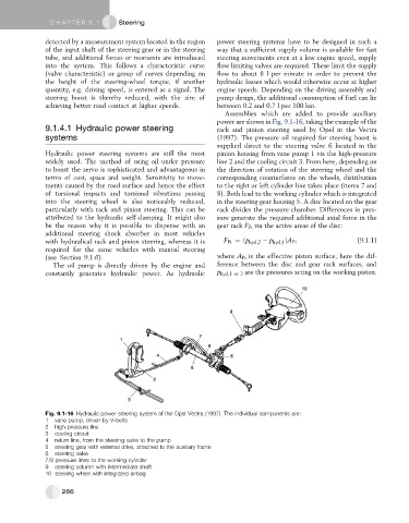
Assemblies which are added to provide auxiliary
power are shown in Fig. 9.1-16, taking the example of the
9.1.4.1 Hydraulic power steering rack and pinion steering used by Opel in the Vectra
systems (1997). The pressure oil required for steering boost is
supplied direct to the steering valve 6 located in the
Hydraulic power steering systems are still the most pinion housing from vane pump 1 via the high-pressure
widely used. The method of using oil under pressure line 2 and the cooling circuit 3. From here, depending on
to boost the servo is sophisticated and advantageous in the direction of rotation of the steering wheel and the
terms of cost, space and weight. Sensitivity to move- corresponding counterforce on the wheels, distribution
ments caused by the road surface and hence the effect to the right or left cylinder line takes place (items 7 and
of torsional impacts and torsional vibrations passing 8). Both lead to the working cylinder which is integrated
into the steering wheel is also noticeably reduced, in the steering-gear housing 5. A disc located on the gear
particularly with rack and pinion steering. This can be rack divides the pressure chamber. Differences in pres-
attributed to the hydraulic self-damping. It might also sure generate the required additional axial force in the
be the reason why it is possible to dispense with an gear rack F Pi via the active areas of the disc:
additional steering shock absorber in most vehicles
with hydraulical rack and pinion steering, whereas it is F Pi ¼ðp hyd;2 p hyd;1 ÞA Pi (9.1.1)
required for the same vehicles with manual steering
(see Section 9.1.6). where A Pi is the effective piston surface, here the dif-
The oil pump is directly driven by the engine and ference between the disc and gear rack surfaces, and
constantly generates hydraulic power. As hydraulic p hyd,1 or 2 are the pressures acting on the working piston.
Fig. 9.1-16 Hydraulic power steering system of the Opel Vectra (1997). The individual components are:
1 vane pump, driven by V-belts
2 high-pressure line
3 cooling circuit
4 return line, from the steering valve to the pump
5 steering gear with external drive, attached to the auxiliary frame
6 steering valve
7/8 pressure lines to the working cylinder
9 steering column with intermediate shaft
10 steering wheel with integrated airbag
266