
Page 267 - Automotive Engineering Powertrain Chassis System and Vehicle Body
P. 267
Steering CHAPTER 9.1
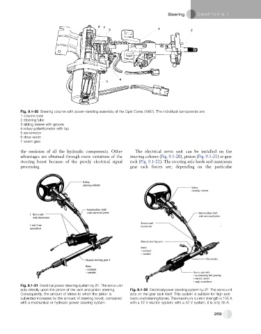
Fig. 9.1-20 Steering column with power-steering assembly of the Opel Corsa (1997). The individual components are:
1 column tube
2 steering tube
3 sliding sleeve with groove
4 rotary potentiometer with tap
5 servomotor
6 drive worm
7 worm gear
the omission of all the hydraulic components. Other The electrical servo unit can be installed on the
advantages are obtained through more variations of the steering column (Fig. 9.1-20), pinion (Fig. 9.1-21) or gear
steering boost because of the purely electrical signal rack (Fig. 9.1-22). The steering axle loads and maximum
processing. gear rack forces are, depending on the particular
Fig. 9.1-21 Electrical power steering system by ZF. The servo unit
acts directly upon the pinion of the rack and pinion steering. Fig. 9.1-22 Electrical power steering system by ZF. The servo unit
Consequently, the amount of stress to which the pinion is acts on the gear rack itself. This system is suitable for high axle
subjected increases by the amount of steering boost, compared loads and steering forces. The maximum current strength is 105 A
with a mechanical or hydraulic power steering system. with a 12 V electric system; with a 42 V system, it is only 35 A.
269