
Page 271 - Automotive Engineering Powertrain Chassis System and Vehicle Body
P. 271
Steering CHAPTER 9.1
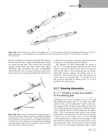
Fig. 9.1-28 Volvo steering column. Both the corrugated tube 1 in the intermediate shaft and the collapsible steering tube 2 meet the
safety requirements. To save weight, the universal joints are made of aluminium alloy Al Mg Si 1 F31 (illustration: Lemfo ¨ rder
Fahrwerktechnik).
the driver pulls the steering wheel abruptly. The dampers in this event the damper generates appropriate forces
therefore increase ride comfort and driving safety, mainly according to the high piston speeds involved.
on manual steering gears. The setting, which generally The dampers are fitted horizontally. As shown in
operates evenly across the whole stroke range, allows Fig. 8.1-57, on rack and pinion steering, one side of the
sufficiently light steerability but stops uncontrollable damper is fixed to the steering rack via an eye or pin-type
wheel vibrations where the front wheels are subjected to joint and the other to the steering housing. On recircu-
uneven lateral and longitudinal vibrational disturbances; lating ball steering systems, the pitman arm on in-
dependent wheel suspensions or the intermediate rod
can be used as a pivot point (Figs. 8.1-39 and 9.1-12)or
the tie rod on rigid axles. As shown in Fig. 9.1-5, this is
parallel to the axle housing.
9.1.7 Steering kinematics
9.1.7.1 Influence of type and position
of the steering gear
Calculating the true tie rod length u 0 (Fig. 9.1-32) and
the steering arm angle l (Fig. 9.1-3) creates some diffi-
culties in the case of independent wheel suspensions.
The position of the steering column influences the posi-
tion of the steering gear by the type of rotational move-
ment. If this deviates from the horizontal by the angle u
(Fig. 9.1-33), a steering gear shaft, which is also inclined
Fig. 9.1-29 ‘Release clutch’ used by VW on steering columns. A by the angle u, becomes necessary. The inner tie rod joint
half-round plate sits on the short shaft that is linked to the steering T which sits on the pitman arm, is carried through
pinion gear, and carries the two pins 1 which point downwards. a three-dimensional arc, influenced by this angle u when
They grip into the two holes of the clutch 2 sitting on the steering the wheels are turned. However, the outer joint U on the
tube from the top. The jacket tube is connected to the dashboard
via a deformable bracket. As shown in a head-on crash, this part 3 steering knuckle whose steering axis is inclined inwards
flexes and the pins 1 slide out of part 2. (Fig. 9.1-34) by the kingpin inclination angle s and is
273