
Page 272 - Automotive Engineering Powertrain Chassis System and Vehicle Body
P. 272
CH AP TER 9 .1 Steering
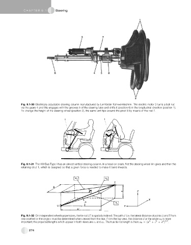
Fig. 9.1-30 Electrically adjustable steering column manufactured by Lemfo ¨ rder Fahrwerktechnik. The electric motor 3 turns a ball nut
via the gears 4 and this engages with the grooves 5 of the steering tube and shifts it (position 6) in the longitudinal direction (position 1).
To change the height of the steering wheel (position 2), the same unit tips around the pivot 8 by means of the rod 7.
Fig. 9.1-31 The VW Bus Type II has an almost vertical steering column. In a head-on crash, first the steering wheel rim gives and then the
retaining strut 1, which is designed so that a given force is needed to make it bend inwards.
0
Fig. 9.1-32 On independent wheel suspensions, the tie rod UT is spatially inclined. The path u (i.e. the lateral distance of points U and T from
one another) or the angle K must be determined when viewed from the rear. From the top view, the distance d or the angle u 0 is more
2 1=2
2
important; the projected lengths which appear in both views are U 1 and u 2 . The true tie rod length is then: u 0 ¼ðu 02 þ c þ d Þ .
274