
Page 273 - Automotive Engineering Powertrain Chassis System and Vehicle Body
P. 273
Steering CHAPTER 9.1
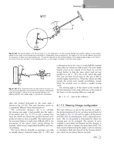
Fig. 9.1-33 The central points of the tie rod joints (T on the inside and U on the outside) change their position relative to one another,
based on the wheel travel (vertical and horizontal) on independent wheel suspensions. The reasons for this are the different directions
of movement of pitman arm and steering arm. The former depends on the inclined position of the steering gear (angle u) and that of
the point U from the inclination of the steering axis EG, i.e. the kingpin inclination s and the caster angle s.
a subsequent rise in the curve to nearly half the nominal
value when the wheels are fully turned. The more highly
loaded wheel on the outside of the bend can even be
turned further in than the inner wheel (and not just
0
parallel to it, Dd z –30 ); due to the higher slip angle
that then has been forced upon it, the tyre is able to
transfer higher lateral forces. When the wheels are fully
turned, the actual curve should, nevertheless, remain
below the nominal curve to achieve a smaller turning
circle.
The steering angle d o of the wheel on the outside of
Fig. 9.1-34 When viewed from the rear, the inner tie rod joint T on
rack and pinion steering moves parallel to the ground, whereas the the bend depends on the angle of the one on the inside of
outer tie rod joint U moves on an arc running vertical to the the bend d i via the steering difference angle Dd:
steering axis EG. Any caster angle s must also be considered.
Dd ¼ d i d o ðaxis of the ordinateÞ
often also inclined backwards by the caster angle s
(shown in Fig. 9.1-33). This joint therefore moves on 9.1.7.2 Steering linkage configuration
a completely different three-dimensional arc.
The construction designer’s job is to calculate The main influences on Dd are the steering arm angle l,
the steering arm angle l (and possibly also the angle o the inclined position of the tie rod when viewed from the
of the pitman arm, Fig. 9.1-37) in such a manner that top (angle 4 o , Fig. 9.1-32) and the angle o of the pitman
when the wheels are turned, the specified desired curve and idler arms on steering gears with a rotational move-
produced comes as close as possible. The achievement of ment. The tie rod position is determined by where the
the necessary balance is made more difficult still by the steering gear can be packaged. The amount of space
movements of the wheel carrier during driving: for available is prescribed and limited and the designer is
example, wheel travel, longitudinal flexibility and verti- unlikely to be able to change it by more than a little. The
cal springing. task consists of determining the angles l and o by drawing
Two curves that are desirable on passenger cars with or calculation. Both also depend on the bearing elastici-
0
an initially almost horizontal shape (Dd z þ30 ) and ties, which are not always known precisely.
275