
Page 276 - Automotive Engineering Powertrain Chassis System and Vehicle Body
P. 276
CH AP TER 9 .1 Steering
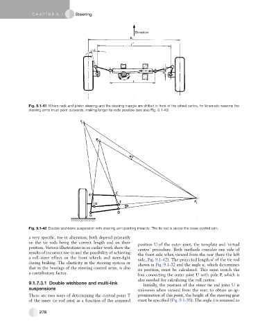
Fig. 9.1-41 Where rack and pinion steering and the steering triangle are shifted in front of the wheel centre, for kinematic reasons the
steering arms must point outwards, making longer tie rods possible (see also Fig. 8.1-40).
Fig. 9.1-42 Double wishbone suspension with steering arm pointing inwards. The tie rod is above the lower control arm.
a very specific, toe-in alteration; both depend primarily
on the tie rods being the correct length and on their position U of the outer joint, the template and ‘virtual
position. Various illustrations in an earlier work show the centre’ procedure. Both methods consider one side of
results of incorrect toe-in and the possibility of achieving the front axle when viewed from the rear (here the left
a roll–steer effect on the front wheels and steer-fight side, Fig. 9.1-42). The projected length u of the tie rod
0
during braking. The elasticity in the steering system or shown in Fig. 9.1-32 and the angle k, which determines
that in the bearings of the steering control arms, is also its position, must be calculated. This must match the
a contributory factor.
line connecting the outer joint U with pole P, which is
also needed for calculating the roll centre.
9.1.7.3.1 Double wishbone and multi-link
Initially, the position of the outer tie rod joint U is
suspensions unknown when viewed from the rear; to obtain an ap-
There are two ways of determining the central point T proximation of this point, the height of the steering gear
of the inner tie rod joint as a function of the assumed must be specified (Fig. 9.1-35). The angle l is assumed so
278