
Page 279 - Automotive Engineering Powertrain Chassis System and Vehicle Body
P. 279
Steering CHAPTER 9.1
(Fig. 9.1-47), P 3 is on the extension of this path. The A low mounted tie rod causes the virtual-centre P 3 to
determining factor for the position of P 1 is the di- move to the right (Fig. 9.1-48) and this then causes
rection of the shift in the damping part of the a shorter rod. This situation is favourable if the inner joint
McPherson strut; for this reason, the vertical in point E needs to sit on the ends of the steering rack. The figures
must be created on its centre-line (not on the steering clearly show that the higher U, which constitutes the
axis EG). The important thing in this calculation is the connection between steering arm and tie-rod, is situated,
position of point U, i.e. the extension of the connecting the longer the tie rods must be, i.e. a centre take-off
line UG downwards. U is shown on the steering axis becomes necessary on a high-mounted rack and pinion
EG simply for reasons of presentation. steering (Figs. 8.1-57, 9.1-11 and 9.1-39).
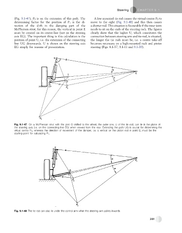
Fig. 9.1-47 On a McPherson strut with the joint G shifted to the wheel, the outer one, U of the tie rod, can lie in the plane of
the steering axis (i.e. on the connecting line EG) when viewed from the rear. Extending the path UG is crucial for determining the
virtual centre P 3 , whereas the direction of movement of the damper, i.e. a vertical on the piston rod in point E, must be the
starting point for calculating P 1 .
Fig. 9.1-48 The tie rod can also lie under the control arm when the steering arm points inwards.
281