
Page 280 - Automotive Engineering Powertrain Chassis System and Vehicle Body
P. 280
CH AP TER 9 .1 Steering
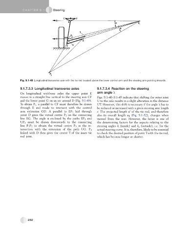
Fig. 9.1-49 Longitudinal transverse axle with the tie rod located above the lower control arm and the steering arm pointing inwards.
9.1.7.3.3 Longitudinal transverse axles 9.1.7.3.4 Reaction on the steering
On longitudinal wishbone axles the upper point E arm angle l
moves in a straight line vertical to the steering axis CF Figs. 9.1-40–9.1-49 indicate that shifting the outer joint
andthe lowerpointG onanarc around D(Fig. 9.1-49). U to the side results in a slight alteration in the distance
To obtain P 1 , a parallel to CF must therefore be drawn UT. However, this shift is necessary if the angle l has to
through E and made to intersect with the control be reduced or increased with a given steering arm length
0
arm extension GD. A parallel to EP 1 laid through r. The projected length u of the tie rod, and therefore
point D gives the virtual centre P 2 on the connecting also its overall length u 0 (Fig. 9.1-32), changes when
line EG. The angle a enclosed by the paths EP 1 and viewed from the rear. However, the latter is one of
UP 1 must be drawn downwards to the connecting the determining factors for the aspects relating to the
line P 1 P 2 to obtain the virtual centre P 3 as the in- steering angles d i (inside) and d o (outside), i.e. for the
tersection with the extension of the path UG. P 3 actual steering curve. It is, therefore, likely to be essential
linked with D then gives the centre T of the inner tie to check the desired position of point Twith the tie rod,
rod joint. which has become longer or shorter.
282