
Page 278 - Automotive Engineering Powertrain Chassis System and Vehicle Body
P. 278
CH AP TER 9 .1 Steering
that is shifted a long way to the right. Where the control
arms are parallel to one another (Figs. 9.1-45), P 1 is at
N. In such cases, a line parallel to the path GD must be
drawn through U and, at the same distance, a further
one drawn through the virtual centre P 2 . The in-
tersection of this second parallel with the extension of
the path UE gives P 3 , which must be linked to C to
obtain T.
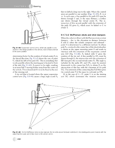
9.1.7.3.2 McPherson struts and strut dampers
When the vehicle is fitted with McPherson struts or strut
dampers – due to the alteration in distance between
E and G when the wheels compress and rebound –
point T is determined by a different method. To obtain
pole P 1 , a vertical to the centre line of the shock absorber
Fig. 9.1-45 Suspension control arms, which are parallel to one
another in the design position of the vehicle, have to have a tie rod is drawn in the upper mounting point E and made to
in the same position. intersect with the extension of the suspension control
arm GD (Fig. 9.1-46); P 1 linked with U gives the
determining factor for the position of virtual-centre P 3 in position of the tie rod. A line parallel to EP 1 must be
the lateral direction. Fig. 9.1-43 shows the case of point drawn through G; the intersection with the extension of
U, which lies left of the path EG. This is something that ED then gives the second virtual-centre P 2 . The angle a,
is only possible where the steering gear is located in front included by the paths EP 1 and UP 1 , must be entered
of the axle (Fig. 9.1-41). P 3 moves to the right, resulting downwards to the connection P 1 P 2 to obtain P 3 as the
in an inner link T moving further away from the centre of intersection of this line with the extension of the path
the vehicle. This is beneficial if it is to be fixed to the end UG. The extension of the connecting line P 3 Dthengives
of the steering rod. the central point T of the inner tie rod joint on UP 1 .
A tie rod that is located above the upper suspension If, in the case of l ¼ 0 , point U is on the steering
control arm (Fig. 9.1-44) causes a large angle a and P 3 axis EG which dominates the rotation movement
Fig. 9.1-46 On the McPherson strut or strut damper, the tie rod is above the lower control arm; the steering arms point inwards with the
result that the outer joint U lies more to the vehicle centre.
280