
Page 274 - Automotive Engineering Powertrain Chassis System and Vehicle Body
P. 274
CH AP TER 9 .1 Steering
Fig. 9.1-35 Path and movement points necessary for determining the tie rod length and position. The position of the tie rods is given
by the connecting line UP (to the pole). The illustration also shows the roll centre Ro.
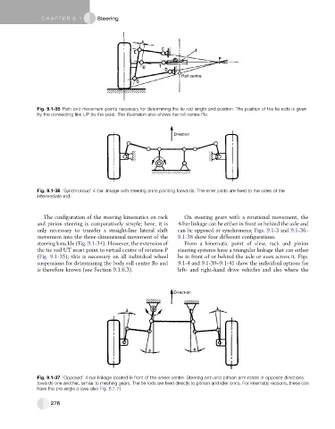
Fig. 9.1-36 ‘Synchronous’ 4-bar linkage with steering arms pointing forwards. The inner joints are fixed to the sides of the
intermediate rod.
The configuration of the steering kinematics on rack On steering gears with a rotational movement, the
and pinion steering is comparatively simple; here, it is 4-bar linkage can be either in front or behind the axle and
only necessary to transfer a straight-line lateral shift can be opposed or synchronous; Figs. 9.1-3 and 9.1-36–
movement into the three-dimensional movement of the 9.1-38 show four different configurations.
steering knuckle (Fig. 9.1-34). However, the extension of From a kinematic point of view, rack and pinion
the tie rod UT must point to virtual centre of rotation P steering systems have a triangular linkage that can either
(Fig. 9.1-35); this is necessary on all individual wheel be in front of or behind the axle or even across it. Figs.
suspensions for determining the body roll centre Ro and 9.1-4 and 9.1-39–9.1-41 show the individual options for
is therefore known (see Section 9.1.6.3). left- and right-hand drive vehicles and also where the
Fig. 9.1-37 ‘Opposed’ 4-bar linkage located in front of the wheel centre. Steering arm and pitman arm rotate in opposite directions
towards one another, similar to meshing gears. The tie rods are fixed directly to pitman and idler arms. For kinematic reasons, these can
have the pre-angle o (see also Fig. 8.1-7).
276