
Page 275 - Automotive Engineering Powertrain Chassis System and Vehicle Body
P. 275
Steering CHAPTER 9.1
Fig. 9.1-38 ‘Opposed’ 4-bar linkage located behind the wheel centre. The inner tie rod joints can be fixed to the middle part of the
intermediate rod or directly to the pitman and idler arm (see Fig. 9.1-12).
Fig. 9.1-39 The rack-and-pinion steering is behind and above the wheel centre and the steering arms point forward (shown for a
right-hand-drive vehicle). For kinematic reasons, the inner tie rod joints are fixed to a central outrigger – known as a central take-off.
This type of solution (also shown in Fig. 8.1-57) is necessary on McPherson and strut damper front axles with a high-location steering
system as the tie rods have to be very long to avoid unwanted steering angles during jounce.
The significantly simpler steering kinematics on rigid
pinion gear must be located – above or below the
steering rack – to make the wheels turn in the direction axles are shown in Figs. 9.1-5–9.1-7.
in which the steering wheel is turned. The steering arms
(negative angles l) which point outwards, shown in 9.1.7.3 Tie rod length and position
Fig. 9.1-41, allow longer tie rods; something which is
useful when the inner joints are pivoted on the ends of When the wheels compress and rebound as well as in
the steering rack. longitudinal movement, there should not be any, or only
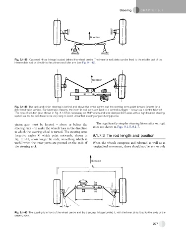
Fig. 9.1-40 The steering is in front of the wheel centre and the triangular linkage behind it, with the inner joints fixed to the ends of the
steering rack.
277