
Page 284 - Automotive Engineering Powertrain Chassis System and Vehicle Body
P. 284
Tyres and wheels C HAPTER 10.1
10.1.2 Tyre designs
10.1.2.1 Diagonal ply tyres
In industrialized countries, cross-ply tyres are no longer
used on passenger cars, either as original tyres or as re-
placement tyres, unlike areas with very poor roads where
the less vulnerable sidewall has certain advantages. The
same is true of commercial vehicles and vehicles that tow
trailers, and here too radial tyres have swept the board
because of their many advantages. Nowadays, cross-ply
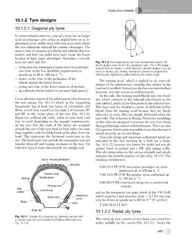
tyres are used only for: Fig. 10.1-2 The diagonal ply tyre has crossed-bias layers; the
zenith angle x was 30–40 for passenger cars. The 4 PR design
temporary use (emergency) spare tyres for passenger should have two layers in each direction. Smaller angles x can be
cars (due to the low durability requirements at found in racing cars. Rolling resistance, lateral and suspension
1
speeds up to 80 or 100 km h ); stiffness are significantly determined by the zenith angle.
motor cycles (due to the inclination of the The running tread, which is applied to the outer di-
wheels against the lateral force);
ameter of the substructure, provides the contact to the
racing cars (due to the lower moment of inertia);
road and is profiled. Some tyres also have an intermediate
agricultural vehicles (which do not reach high speeds).
structure over the carcass as reinforcement.
At the side, the running tread blends into the shoul-
Cross-ply tyres consist of the substructure (also known as der, which connects to the sidewall (also known as the
the tyre carcass, Fig. 10.1-1) which, as the ‘supporting side rubber), and is a layer that protects the substructure.
framework’ has at least two layers of rubberized cord This layer and the shoulders consist of different rubber
fibres, which have a zenith or bias angle x of between 20 blends from the running tread because they are barely
and 40 to the centre plane of the tyre (Fig. 10.1-2). subjected to wear; they are simply deformed when the
Rayon (an artificial silk cord), nylon or even steel cord tyre rolls. This is known as flexing. Protective mouldings
may be used, depending on the strength requirements. on the sides are designed to prevent the tyre from being
At the tyre feet the ends of the layers are wrapped damaged through contact with kerbstones. There are also
around the core of the tyre bead on both sides; two wire GG grooves, which make it possible to see that the tyre is
rings, together with the folded ends of the plies, form the seated properly on the rim flange.
bead. This represents the frictional connection to the Cross-ply design and maximum authorized speed are
rim. The bead must thus provide the permanent seat and indicated in the tyre marking by a dash (or a letter,
transfer drive-off and braking moments to the tyre. On Fig. 10.1-12) between the letters for width and rim di-
tube-less tyres it must also provide the airtight seal. ameter (both in inches) and a ‘PR’ (ply rating) suffix.
This ply rating refers to the carcass strength and simply
indicates the possible number of plies (Fig. 10.1-5). The
Cap of the tyre (protector) marking convention is:
Shoulder
5.60-15/4 PR (VW rear-engine passenger car, tyres
1
authorized up to 150 km h )
Breaker strip 7.00-14/8 PR (VW Transporter, tyres authorized up
1
Skirting Substructure to 150 km h )
9.00-20/14 PR (reinforced design for a commercial
Flexing zone vehicle)
Wall
rubber Inner lining and on the temporary use spare wheel of the VW Golf,
Installation which requires a tyre pressure of p T ¼ 4.2 bar and may
Bead core
curve only be driven at speeds up to 80 km h 1 (F symbol)
Bead
Valve
T 105/70 D 14 38 F
Drop rim
10.1.2.2 Radial ply tyres
Fig. 10.1-1 Design of a diagonal ply tubeless car tyre with
a normal drop rim and pressed-in inflating valve (see also The radial ply tyre consists of two bead cores joined to-
Fig. 10.1-6). gether radially via the carcass (Fig. 10.1-3) – hence the
287