
Page 287 - Automotive Engineering Powertrain Chassis System and Vehicle Body
P. 287
CHAP TER 1 0. 1 Tyres and wheels
00
Valves are needed for inflating the tyre and maintaining 1 ¼ 1in ¼ 25:4 mm (10.1.1a)
the required pressure. Various designs are available for
tubeless and tubed tyres (Figs. 10.1-6 and 10.1-7). The The 175/65 R 14 82 H tyre mounted on the measuring
most widely used valve is the so-called ‘snap-in valve’. It rim 5J 14 can be taken as an example:
comprises a metal foot valve body vulcanized into a rubber
sheath, which provides the seal in the rim hole (Fig. 10.1-20). OD T ¼ 584 mm; d ¼ 14 25:4
The functionality is achieved by a valve insert, while a cap ¼ 356 mm and W ¼ 177 mm
closes the valve and protects it against ingress of dirt. H=W ¼½0:5 ðOD T dÞ=W ¼ 114=177 ¼ 0:644
At high speeds, the valve can be subjected to bending
stress and loss of air can occur. Hub caps and support The cross-section ratio is rounded to two digits and given
areas on alloy wheels can help to alleviate this (see as a percentage. We talk of ‘series’, and here the ratio
Fig. 10.1-24). profile is 65% as shown in the tyre marking – in other
words it is a 65 series tyre. A wider rim, e.g. 6J 14
10.1.2.4 Height-to-width ratio would give a smaller percentage.
The height-to-width ratio H/W – also known as the 10.1.2.5 Tyre dimensions and markings
‘profile’ (high or low) – influences the tyre properties and
affects how much space the wheel requires (Fig. 10.1-8). 10.1.2.5.1 Designations for passenger cars up
As shown in Fig. 10.1-9, the narrower tyres with a H/W to 270 km h –1
ratio ¼ 0.70 have a reduced tread and therefore good
aquaplaning behaviour (Fig. 10.1-35). Wide designs make The standards manual of the European Tire and Rim
it possible to have a larger diameter rim and bigger brake Technical Organization (ETRTO) includes all tyres for
1
discs (Fig. 10.1-10) and can also transmit higher lateral passenger cars and delivery vehicles up to 270 km h
and longitudinal forces. and specifies the following data:
W is the cross-sectional width of the new tyre tyre width in mm
(Fig. 10.1-11); the height H can easily be calculated from height-to-width ratio as a percentage
the rim diameter given in inches and the outside di- code for tyre design
ameter of the tyre OD T . The values OD T and Ware to be rim diameter in inches or mm
taken from the new tyre mounted onto a measuring rim operational identification, comprising load index; LI
at a measuring tyre pressure of 1.8 bar or 2.3 bar on (carrying capacity index) and speed symbol GSY.
V-, W- or ZR tyres, Fig. 10.1-15):
H ¼ 0:5ðOD T dÞ (10.1.1) The following applies to the type shown in Fig. 10.1-15:
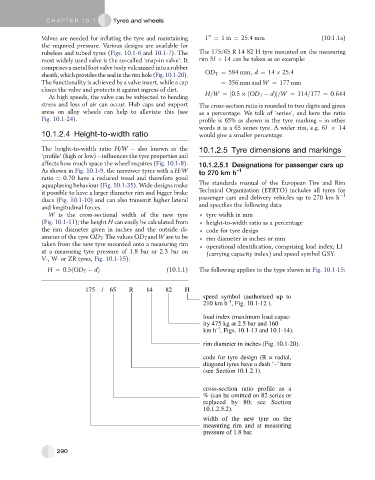
175 / 65 R 14 82 H
speed symbol (authorized up to
–1
210 km h , Fig. 10.1-12 ).
load index (maximum load capac-
ity 475 kg at 2.5 bar and 160
–1
km h , Figs. 10.1-13 and 10.1-14).
rim diameter in inches (Fig. 10.1-20).
code for tyre design (R = radial,
diagonal tyres have a dash ‘–’ here
(see Section 10.1.2.1).
cross-section ratio profile as a
% (can be omitted on 82 series or
replaced by 80; see Section
10.1.2.5.2).
width of the new tyre on the
measuring rim and at measuring
pressure of 1.8 bar.
290