
Page 261 - Automotive Engineering Powertrain Chassis System and Vehicle Body
P. 261
Steering CHAPTER 9.1
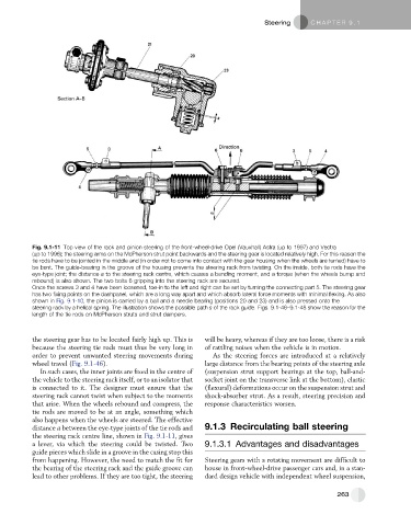
Fig. 9.1-11 Top view of the rack and pinion steering of the front-wheel-drive Opel (Vauxhall) Astra (up to 1997) and Vectra
(up to 1996); the steering arms on the McPherson strut point backwards and the steering gear is located relatively high. For this reason the
tie rods have to be jointed in the middle and (in order not to come into contact with the gear housing when the wheels are turned) have to
be bent. The guide-bearing in the groove of the housing prevents the steering rack from twisting. On the inside, both tie rods have the
eye-type joint; the distance a to the steering rack centre, which causes a bending moment, and a torque (when the wheels bump and
rebound) is also shown. The two bolts 6 gripping into the steering rack are secured.
Once the screws 3 and 4 have been loosened, toe-in to the left and right can be set by turning the connecting part 5. The steering gear
has two fixing points on the dashpanel, which are a long way apart and which absorb lateral force moments with minimal flexing. As also
shown in Fig. 9.1-10, the pinion is carried by a ball and a needle bearing (positions 20 and 23) and is also pressed onto the
steering rack by a helical spring. The illustration shows the possible path s of the rack guide. Figs. 9.1-46–9.1-48 show the reason for the
length of the tie rods on McPherson struts and strut dampers.
the steering gear has to be located fairly high up. This is will be heavy, whereas if they are too loose, there is a risk
because the steering tie rods must thus be very long in of rattling noises when the vehicle is in motion.
order to prevent unwanted steering movements during As the steering forces are introduced at a relatively
wheel travel (Fig. 9.1-46). large distance from the bearing points of the steering axle
In such cases, the inner joints are fixed in the centre of (suspension strut support bearings at the top, ball-and-
the vehicle to the steering rack itself, or to an isolator that socket joint on the transverse link at the bottom), elastic
is connected to it. The designer must ensure that the (flexural) deformations occur on the suspension strut and
steering rack cannot twist when subject to the moments shock-absorber strut. As a result, steering precision and
that arise. When the wheels rebound and compress, the response characteristics worsen.
tie rods are moved to be at an angle, something which
also happens when the wheels are steered. The effective
distance a between the eye-type joints of the tie rods and 9.1.3 Recirculating ball steering
the steering rack centre line, shown in Fig. 9.1-11, gives
a lever, via which the steering could be twisted. Two 9.1.3.1 Advantages and disadvantages
guide pieces which slide in a groove in the casing stop this
from happening. However, the need to match the fit for Steering gears with a rotating movement are difficult to
the bearing of the steering rack and the guide groove can house in front-wheel-drive passenger cars and, in a stan-
lead to other problems. If they are too tight, the steering dard design vehicle with independent wheel suspension,
263