
Page 327 - Automotive Engineering Powertrain Chassis System and Vehicle Body
P. 327
CHAP TER 1 1. 1 Tyre characteristics and vehicle handling and stability
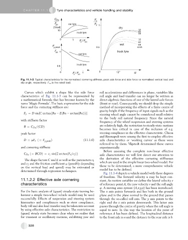
Fig. 11.1-3 Typical characteristics for the normalised cornering stiffness, peak side force and side force vs normalised vertical load and
slip angle, respectively. F zo is the rated load.
Curves which exhibit a shape like the side force roll accelerations and differences in phase, variables like
characteristics of Fig. 11.1-3 can be represented by roll angle and load transfer can no longer be written as
a mathematical formula that has become known by the direct algebraic functions of one of the lateral axle forces
name ‘Magic Formula’. The basic expressions for the side (front or rear). Consequently, we should drop the simple
force and the cornering stiffness are: method of incorporating the effects of a finite centre of
gravity height if the frequency of input signals such as the
F y ¼ D sin½C arctanfBa EðBa arctanðBaÞÞg steering wheel angle cannot be considered small relative
to the body roll natural frequency. Since the natural
with stiffness factor
frequency of the wheel suspension and steering systems
B ¼ C Fa =ðCDÞ are relatively high, the restriction to steady-state motions
becomes less critical in case of the inclusion of e.g.
peak factor steering compliance in the effective characteristic. Chiesa
and Rinonapoli were among the first to employ effective
D ¼ mF z ð¼ F y;peak Þ (11.1.6) axle characteristics or ‘working curves’ as these were
referred to by them. Va ˚gstedt determined these curves
and cornering stiffness experimentally.
Before assessing the complete non-linear effective
C Fa ð¼ BCDÞ¼ c 1 sinf2 arctanðF z =c 2 Þg axle characteristics we will first direct our attention to
the derivation of the effective cornering stiffnesses
The shape factors C and E as well as the parameters c 1
and c 2 and the friction coefficient m (possibly depending which are used in the simple linear two-wheel model. For
these to be determined, a more comprehensive vehicle
on the vertical load and speed) may be estimated or
model has to be defined.
determined through regression techniques.
Fig. 11.1-4 depicts a vehicle model with three degrees
of freedom. The forward velocity u may be kept con-
11.1.2.2 Effective axle cornering stant. As motion variables we define the lateral velocity n
characteristics of reference point A, the yaw velocity r and the roll angle
4. A moving axes system (A,x,y,z) has been introduced.
For the basic analysis of (quasi) steady-state turning be- The x axis points forwards and lies both in the ground
haviour a simple two-wheel vehicle model may be used plane and in the plane normal to the ground that passes
successfully. Effects of suspension and steering system through the so-called roll axis. The y axis points to the
kinematics and compliances such as steer compliance, right and the z axis points downwards. This latter axis
body roll and also load transfer may be taken into account passes through the centre of gravity when the roll angle is
by using effective axle characteristics. The restriction to equal to zero. In this way the location of the point of
(quasi) steady state becomes clear when we realise that reference A has been defined. The longitudinal distance
for transient or oscillatory motions, exhibiting yaw and to the front axle is a and the distance to the rear axle is b.
328