
Page 332 - Automotive Engineering Powertrain Chassis System and Vehicle Body
P. 332
Tyre characteristics and vehicle handling and stability C HAPTER 11.1
F [N] | F | of an automobile that runs at constant speed over an even
y,tyre F z,tyre z
horizontal road and thereby gain considerable insight into
8000 4000 the basic aspects of vehicle handling and stability. Im-
7000 3000
6000 2000 portant early work on the linear theory of vehicle handling
5000 5000 1000 and stability has been published by Riekert and Schunck;
4000 0
[N]
3000 1000 Whitcomb and Milliken; and Segel. Pevsner studied the
2000 2000 non-linear steady-state cornering behaviour at larger lat-
1000 3000
0 o 0 4000 eral accelerations and introduced the handling diagram.
10 One of the first more complete vehicle model studies has
F
y,axle been conducted by Pacejka and by Radt and Pacejka.
The derivation of the equations of motion for the
5000
?? three-degree-of-freedom model of Fig. 11.1-4 will be
treated first after which the simple model with two
degrees of freedom is considered and analysed. This
F 0 10 o analysis comprises the steady-state response to steering
z 4000 3000 2000 1000 input and the stability of the resulting motion. Also,
the frequency response to steering fluctuations and
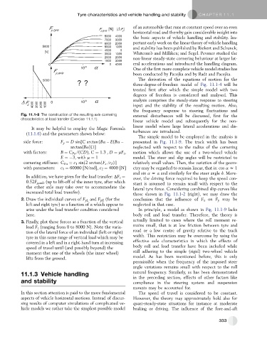
Fig. 11.1-8 The construction of the resulting axle cornering external disturbances will be discussed, first for the
characteristics at load transfer (Exercise 11.1.1).
linear vehicle model and subsequently for the non-
linear model where large lateral accelerations and dis-
It may be helpful to employ the Magic Formula
(11.1.6) and the parameters shown below: turbances are introduced.
The simple model to be employed in the analysis is
side force: F y ¼ D sin[C arctan{Ba –E(Ba – presented in Fig. 11.1-9. The track width has been
arctan(Ba))}] neglected with respect to the radius of the cornering
with factors: B ¼ C Fa /(CD), C ¼ 1.3 , D ¼ mF z , motion which allows the use of a two-wheel vehicle
E ¼ 3, with m ¼ 1 model. The steer and slip angles will be restricted to
cornering stiffness: C Fa ¼ c 1 sin[2 arctan{F z /c 2 }] relatively small values. Then, the variation of the geom-
with parameters: c 1 ¼ 60000 [N/rad], c 2 ¼ 4000 [N] etry may be regarded to remain linear, that is: cos a z 1
and sin a z a and similarly for the steer angle d. More-
In addition, we have given for the load transfer: DF z ¼ over, the driving force required to keep the speed con-
0.52F y,axle (up to lift-off of the inner tyre, after which stant is assumed to remain small with respect to the
the other axle may take over to accommodate the lateral tyre force. Considering combined slip curves like
increased total load transfer). those shown in Fig. 11.1-2 (right), we may draw the
2. Draw the individual curves of F yL and F yR (for the conclusion that the influence of F x on F y may be
left and right tyre) as a function of a which appear to neglected in that case.
arise under the load transfer condition considered In principle, a model as shown in Fig. 11.1-9 lacks
here. body roll and load transfer. Therefore, the theory is
3. Finally, plot these forces as a function of the vertical actually limited to cases where the roll moment re-
load F z (ranging from 0 to 8000 N). Note the varia- mains small, that is at low friction between tyre and
tion of the lateral force of an individual (left or right) road or a low centre of gravity relative to the track
tyre in this same range of vertical load which may be width. This restriction may be overcome by using the
covered in a left and in a right-hand turn at increasing effective axle characteristics in which the effects of
speed of travel until (and possibly beyond) the body roll and load transfer have been included while
moment that one of the wheels (the inner wheel) still adhering to the simple (rigid) two-wheel vehicle
lifts from the ground. model. As has been mentioned before, this is only
permissible when the frequency of the imposed steer
angle variations remains small with respect to the roll
11.1.3 Vehicle handling natural frequency. Similarly, as has been demonstrated
in the preceding section, effects of other factors like
and stability compliance in the steering system and suspension
mounts may be accounted for.
In this section attention is paid to the more fundamental The speed of travel is considered to be constant.
aspects of vehicle horizontal motions. Instead of discus- However, the theory may approximately hold also for
sing results of computer simulations of complicated ve- quasi-steady-state situations for instance at moderate
hicle models we rather take the simplest possible model braking or driving. The influence of the fore-and-aft
333