
Page 328 - Automotive Engineering Powertrain Chassis System and Vehicle Body
P. 328
Tyre characteristics and vehicle handling and stability C HAPTER 11.1
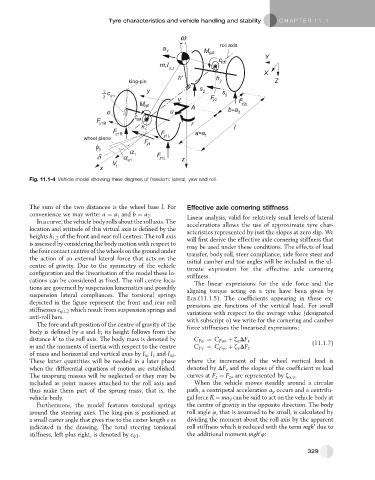
Fig. 11.1-4 Vehicle model showing three degrees of freedom: lateral, yaw and roll.
The sum of the two distances is the wheel base l.For Effective axle cornering stiffness
convenience we may write: a ¼ a 1 and b ¼ a 2 . Linear analysis, valid for relatively small levels of lateral
In a curve, the vehicle body rolls about the roll axis. The accelerations allows the use of approximate tyre char-
location and attitude of this virtual axis is defined by the
acteristics represented by just the slopes at zero slip. We
heights h 1,2 of the front and rear roll centres. The roll axis will first derive the effective axle cornering stiffness that
is assessed by considering the body motion with respect to may be used under these conditions. The effects of load
the fourcontact centres ofthe wheels on the groundunder transfer, body roll, steer compliance, side force steer and
the action of an external lateral force that acts on the initial camber and toe angles will be included in the ul-
centre of gravity. Due to the symmetry of the vehicle timate expression for the effective axle cornering
configuration and the linearisation of the model these lo- stiffness.
cations can be considered as fixed. The roll centre loca- The linear expressions for the side force and the
tions are governed by suspension kinematics and possibly aligning torque acting on a tyre have been given by
suspension lateral compliances. The torsional springs Eqs.(11.1.5). The coefficients appearing in these ex-
depicted in the figure represent the front and rear roll pressions are functions of the vertical load. For small
stiffnesses c 41,2 which result from suspension springs and variations with respect to the average value (designated
anti-roll bars. with subscript o) we write for the cornering and camber
The fore and aft position of the centre of gravity of the force stiffnesses the linearised expressions:
body is defined by a and b; its height follows from the
0
distance h to the roll axis. The body mass is denoted by C Fa ¼ C Fao þ z a DF z (11.1.7)
m and the moments of inertia with respect to the centre C Fg ¼ C Fgo þ z g DF z
of mass and horizontal and vertical axes by I x , I z and I xz .
These latter quantities will be needed in a later phase where the increment of the wheel vertical load is
when the differential equations of motion are established. denoted by DF z and the slopes of the coefficient vs load
The unsprung masses will be neglected or they may be curves at F z ¼ F zo are represented by z a,g .
included as point masses attached to the roll axis and When the vehicle moves steadily around a circular
thus make them part of the sprung mass, that is, the path, a centripetal acceleration a y occurs and a centrifu-
vehicle body. gal force K ¼ ma y can be said to act on the vehicle body at
Furthermore, the model features torsional springs the centre of gravity in the opposite direction. The body
around the steering axes. The king-pin is positioned at roll angle 4, that is assumed to be small, is calculated by
a small caster angle that gives rise to the caster length e as dividing the moment about the roll axis by the apparent
0
indicated in the drawing. The total steering torsional roll stiffness which is reduced with the term mgh due to
0
stiffness, left plus right, is denoted by c j1 . the additional moment mgh 4:
329