
Page 331 - Automotive Engineering Powertrain Chassis System and Vehicle Body
P. 331
CHAP TER 1 1. 1 Tyre characteristics and vehicle handling and stability
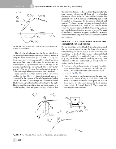
the inner tyre. Because of the non-linear degressive F y vs F z
curve, however, the average side force will be smaller than
the original value it had in the absence of load transfer. The
graph indicates that an increase Da of the slip angle would
be needed to compensate for the adverse effect of load
transfer. The lower diagram gives a typical example of the
change in characteristic as a result of load transfer. At the
origin the slope is not affected but at larger slip angles an
increasingly lower derivative appears to occur. The peak
diminishes and may even disappear completely. The way to
determine the resulting characteristic is the subject of the
next exercise.
Exercise 11.1.1. Construction of effective axle
characteristic at load transfer
Fig. 11.1-6 Effective front axle characteristic F y1 (a a1 ) influenced For a series of tyre vertical loads F z the characteristics of
by steering compliance.
the two tyres mounted on, say, the front axle of an au-
tomobile are given. In addition, it is known how the load
The effective axle characteristic for the case of roll steer transfer DF z at the front axle depends on the centrifugal
can be easily established by subtracting j ri from a i .Instead of force K ( ¼ mgF y1 /F z1 ¼ mg F y2 /F z2 ) acting at the centre
using the linear relationships (11.1.8)and (11.1.13)non- of gravity. From this data the resulting cornering char-
linear curves may be adopted, possibly obtained from mea- acteristic of the axle considered (at steady-state cor-
surements. For the case of roll camber, the situation becomes nering) can be determined.
morecomplex.Atagivenaxlesideforcetheroll angleandthe
associated camber angle can be found. The cornering char- 1. Find the resulting characteristic of one axle from the
acteristic of the pair of tyres at that camber angle is needed to set of individual tyre characteristics at different tyre
findthe slipanglebelonging to thesideforce considered. loads F z and the load transfer characteristic (both
Load transfer is another example that is less easy to shown in Fig. 11.1-8).
handle. In Fig. 11.1-7 a three-dimensional graph is Hint: First draw in the lower diagram the axle char-
presented for the variation of the side force of an individual acteristics for values of DF z ¼ 1000, 2000, 3000 and
tyre as a function of the slip angle and of the vertical load. 4000 N and then determine which point on each of
Theformeratagivenloadandthelatteratagivenslipangle. these curves is valid considering the load transfer
The diagram illustrates that at load transfer the outer tyre characteristic (left-hand diagram). Then, draw the
exhibiting a larger load will generate a larger side force than resulting axle characteristic.
F F
y y
tyre tyre
ma y
L R
0 F
y
0 F + F F - F z axle
zo
zo
z
F z
F
z
F
y axle
0 axle
Fig. 11.1-7 The influence of load transfer on the resulting axle characteristic.
332