
Page 330 - Automotive Engineering Powertrain Chassis System and Vehicle Body
P. 330
Tyre characteristics and vehicle handling and stability C HAPTER 11.1
The axle side force is the sum of the left and right running, side forces are already present through the in-
individual tyre side forces. We have: troduction of e.g. opposite steer and camber angles. If these
anglesareabsent, theinfluenceofloadtransferispurelynon-
F yiL ¼ð½C Fai þ z ai DF zi Þða i j Þ linear and is only felt at higher levels of lateral accelerations.
io
In the next subsection, this non-linear effect will be in-
þð½C Fgi þ z gi DF zi Þðg g Þ corporated in theeffectiveaxlecharacteristic.
io
i
F yiR ¼ð½C Fai z ai DF zi Þða i þ j Þ (11.1.19)
io
þð½C Fgi z gi DF zi Þðg þg Þ Effective non-linear axle characteristics
io
i
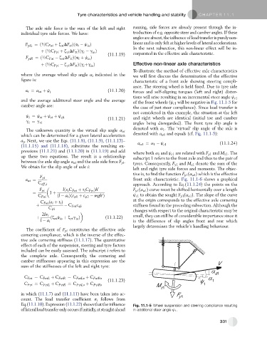
To illustrate the method of effective axle characteristics
where the average wheel slip angle a i indicated in the we will first discuss the determination of the effective
figure is: characteristic of a front axle showing steering compli-
ance. The steering wheel is held fixed. Due to tyre side
a i ¼ a ai þ j i (11.1.20) forces and self-aligning torques (left and right) distor-
tions will arise resulting in an incremental steer angle j c1
and the average additional steer angle and the average of the front wheels (j c1 will be negative in Fig. 11.1-5 for
camber angle are: the case of just steer compliance). Since load transfer is
not considered in this example, the situation at the left
j ¼ j þ j þ j sfi (11.1.21) and right wheels are identical (initial toe and camber
ri
ci
i
g ¼ g ri angles being disregarded). The front tyre slip angle is
i
denoted with a 1 . The ‘virtual’ slip angle of the axle is
The unknown quantity is the virtual slip angle a ai
which can be determined for a given lateral acceleration denoted with a a1 and equals (cf. Fig. 11.1-5):
a y . Next, we use the Eqs. (11.1.8), (11.1.9), (11.1.13)– (11.1.24)
(11.1.15) and (11.1.18), substitute the resulting ex- a a1 ¼ a 1 j c1
pressions (11.1.21) and (11.1.20)in(11.1.19) and add where both a 1 and j c1 are related with F y1 and M z1 . The
up these two equations. The result is a relationship subscript 1 refers to the front axle and thus to the pair of
between the axle slip angle a ai and the axle side force F yi . tyres. Consequently, F y1 and M z1 denote the sum of the
We obtain for the slip angle of axle i: left and right tyre side forces and moments. The objec-
tive is, to find the function F y1 (a a1 ) which is the effective
F yi
a ai ¼ front axle characteristic. Fig. 11.1-6 shows a graphical
C eff;i approach. According to Eq.(11.1.24) the points on the
F yi lð3 i C Fai þ s i C Fgi Þh 0 F y1 (a a1 ) curve must be shifted horizontally over a length
¼ 1 þ 0
C Fai ðl a i Þðc 41 þ c 42 mgh Þ j c1 to obtain the sought F y1 (a a1 ). The slope of the curve
C Fai ðe i þ t i Þ at the origin corresponds to the effective axle cornering
þ C Fai c sfi stiffness found in the preceding subsection. Although the
C ji
changes with respect to the original characteristic may be
2ls i small, they can still be of considerable importance since it
þ ðz ai j þ z gi g Þ (11.1.22)
io
io
l a i is the difference of slip angles front and rear which
largely determines the vehicle’s handling behaviour.
The coefficient of F yi constitutes the effective axle
cornering compliance, which is the inverse of the effec-
tive axle cornering stiffness (11.1.17). The quantitative
effect of each of the suspension, steering and tyre factors
included can be easily assessed. The subscript i refers to
the complete axle. Consequently, the cornering and
camber stiffnesses appearing in this expression are the V
sum of the stiffnesses of the left and right tyre:
a1
C Fai ¼ C FaiL þ C FaiR ¼ C FaiLo þ C FaiRo
(11.1.23) 1
C Fgi ¼ C FgiL þ C FgiR ¼ C FgiLo þ C FgiRo 1
M
z1
in which (11.1.7)and (11.1.11) have been taken into ac- F
count. The load transfer coefficient s i follows from y1
Eq.(11.1.10). Expression (11.1.22) shows thatthe influence Fig. 11.1-5 Wheel suspension and steering compliance resulting
oflateralloadtransferonlyoccursifinitially,atstraightahead in additional steer angle j 1 .
331