
Page 442 - Automotive Engineering Powertrain Chassis System and Vehicle Body
P. 442
Decisional architecture C HAPTER 14.2
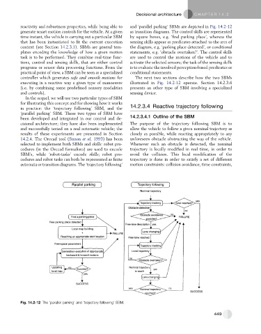
reactivity and robustness properties, while being able to and ‘parallel parking’ SBMs are depicted in Fig. 14.2-12
generate smart motion controls for the vehicle. At a given as transition diagrams. The control skills are represented
time instant, the vehicle is carrying out a particular SBM by square boxes, e.g. ‘find parking place’, whereas the
that has been instantiated to fit the current execution sensing skills appear as predicates attached to the arcs of
context (see Section 14.2.3.1). SBMs are general tem- the diagram, e.g. ‘parking place detected’, or conditional
plates encoding the knowledge of how a given motion statements, e.g. ‘obstacle overtaken?’. The control skills
task is to be performed. They combine real-time func- are used to control the motions of the vehicle and to
tions, control and sensing skills, that are either control activate the selected sensors; the task of the sensing skills
programs or sensor data processing functions. From the is to evaluate the involved perception-based predicates or
practical point of view, a SBM can be seen as a specialized conditional statements.
controller which generates safe and smooth motions for The next two sections describe how the two SBMs
executing in a reactive way a given type of manoeuvre illustrated in Fig. 14.2-12 operate. Section 14.2.3.6
(i.e. by combining some predefined sensory modalities presents an other type of SBM involving a specialized
and controls). sensing device.
In the sequel, we will use two particular types of SBM
for illustrating this concept and for showing how it works
in practice: the ‘trajectory following’ SBM, and the 14.2.3.4 Reactive trajectory following
‘parallel parking’ SBM. These two types of SBM have
been developed and integrated in our control and de- 14.2.3.4.1 Outline of the SBM
cisional architecture; they have also been implemented The purpose of the trajectory following SBM is to
and successfully tested on a real automatic vehicle; the allow the vehicle to follow a given nominal trajectory as
results of these experiments are presented in Section closely as possible, while reacting appropriately to any
14.2.4. The Orccad tool (Simon et al, 1993) has been unforeseen obstacle obstructing the way of the vehicle.
selected to implement both SBMs and skills: robot pro- Whenever such an obstacle is detected, the nominal
cedures (in the Orccad formalism) are used to encode trajectory is locally modified in real time, in order to
SBM’s, while ‘robot-tasks’ encode skills; robot pro- avoid the collision. This local modification of the
cedures and robot tasks can both be represented as finite trajectory is done in order to satisfy a set of different
automata or transition diagrams. The ‘trajectory following’ motion constraints: collision avoidance, time constraints,
Fig. 14.2-12 The ’parallel parking’ and ‘trajectory following’ SBM.
449