
Page 441 - Automotive Engineering Powertrain Chassis System and Vehicle Body
P. 441
CHAP TER 1 4. 2 Decisional architecture
Our control and decisional architecture features three be handled by the current SBM happens (e.g. the in-
main components, the Mission scheduler, the Motion plan- trusion of an unexpected obstacle which cannot be
ner and the Motion controller, which are described below. avoided using the current control skills), the Motion
controller reports a failure to the mission scheduler which
14.2.3.1.1 Mission scheduler updates the current PMP either by applying a re-planning
When given a mission description, e.g. ‘park at location l’, procedure (time permitting), or by selecting in real-time
the Mission scheduler generates a parameterized motion an SBM adapted to the new situation.
plan (PMP) which is an ordered set of generic SBMs
possibly completed with nominal trajectories. The SBMs 14.2.3.2 Models of the vehicles
are selected from an SBM library, according to the cur-
rent execution context. An SBM may require a nominal The Sharp control and decisional architecture has been
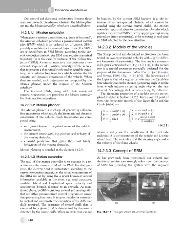
trajectory (as is the case for instance of the ‘follow tra- tested on two experimental vehicles with slightly differ-
jectory’ SBM). A nominal trajectory is a continuous time- ent kinematic characteristics. The first one is a commer-
ordered sequence of (position, velocity) of the vehicle cial Ligier electrical vehicle (Fig. 14.2-11(a)). The second
that represents a theoretically safe and executable trajec- one is a special prototype especially designed for the
tory, i.e. a collision free trajectory which satisfies the ki- purpose of the Automated Public Car project (Laugier
nematic and dynamic constraints of the vehicle. When and Parent, 1999)(Fig. 14.2-11(b)). The kinematics of
they are needed, such trajectories are computed by the the Ligier is that of a regular car whereas the Cycab has
Motion planner, under the request of the Mission four wheels that can be steered (a steering angle f on the
scheduler. front wheels induces a steering angle kf on the rear
The involved SBMs, along with their associated wheels). Accordingly, its kinematics is slightly different.
nominal trajectories, are passed to the Motion controller The kinematic properties of a car-like vehicle are ex-
for their reactive executions. plored in detail in Section 14.2.5. From a control point of
view, the respective models of the Ligier (left) and the
14.2.3.1.2 Motion planner Cycab (right) are:
The Motion planner is in charge of generating collision- 8 _ x ¼ v cosðq þ fÞ 8 _ x ¼ v cosðq þ fÞ
>
free trajectories which satisfy the kinematic and dynamic < _ y ¼ v cosðq þ fÞ < _ y ¼ v cosðq þ fÞ
constraints of the vehicle. Such trajectories are com- : q ¼ v sin f > q ¼ v sinðf þ kfÞ
: _
_
puted using: L L cosðkfÞ
an a priori known or acquired model of the vehicle (14.2.1)
environment,
the current sensor data, e.g. position and velocity of where x and y are the coordinates of the front axle
the moving obstacles, midpoint, q is the orientation of the vehicle and L is the
wheel base. The controls are f the steering angle and v
a world prediction that gives the most likely the velocity of the front wheels.
behaviours of the moving obstacles.
Motion planning is detailed in the Section 14.2.5. 14.2.3.3 Concept of SBM
14.2.3.1.3 Motion controller As has previously been mentioned, our control and
The goal of the motion controller is to execute in a re- decisional architecture strongly relies upon the concept
active way the current SBM of the PMP. For that pur- of SBM for providing the system with the required
pose, the current SBM is instantiated according to the
current execution context, i.e. the variable parameters of
the SBM are set by using the a priori known or sensed
information available at the time, e.g. road curvature,
available lateral and longitudinal space, velocity and
acceleration bounds, distance to an obstacle. As men-
tioned above, an SBM combines control and sensing skills
that are either parameterized control programs or sensor
data processing functions. It is up to the Motion controller
to control and coordinate the execution of the different
skills required. The sequence of control skills that is
executed for a given SBM is determined by the events
detected by the sensor skills. When an event that cannot Fig. 14.2-11 The Ligier vehicle (a), and the Cycab (b).
448