
Page 469 - Automotive Engineering Powertrain Chassis System and Vehicle Body
P. 469
Modelling and assembly of the full vehicle C HAPTER 15.1
Z 2
X 2
G 2 ,O 2
Body 2
Y 2
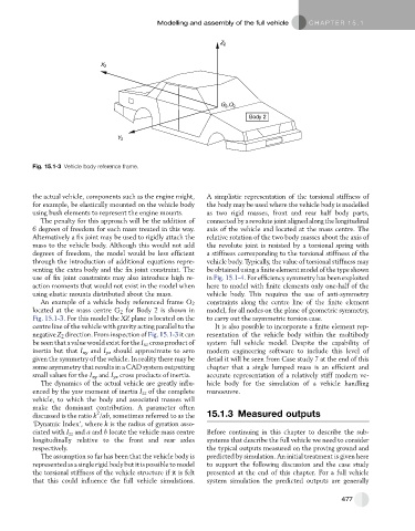
Fig. 15.1-3 Vehicle body reference frame.
the actual vehicle, components such as the engine might, A simplistic representation of the torsional stiffness of
for example, be elastically mounted on the vehicle body the body may be used where the vehicle body is modelled
using bush elements to represent the engine mounts. as two rigid masses, front and rear half body parts,
The penalty for this approach will be the addition of connected by a revolute joint aligned along the longitudinal
6 degrees of freedom for each mass treated in this way. axis of the vehicle and located at the mass centre. The
Alternatively a fix joint may be used to rigidly attach the relative rotation of the two body masses about the axis of
mass to the vehicle body. Although this would not add the revolute joint is resisted by a torsional spring with
degrees of freedom, the model would be less efficient a stiffness corresponding to the torsional stiffness of the
through the introduction of additional equations repre- vehicle body. Typically, the value of torsional stiffness may
senting the extra body and the fix joint constraint. The be obtained using a finite element model of the type shown
use of fix joint constraints may also introduce high re- in Fig. 15.1-4. For efficiency symmetry has been exploited
action moments that would not exist in the model when here to model with finite elements only one-half of the
using elastic mounts distributed about the mass. vehicle body. This requires the use of anti-symmetry
An example of a vehicle body referenced frame O 2 constraints along the centre line of the finite element
located at the mass centre G 2 for Body 2 is shown in model, for all nodes on the plane of geometric symmetry,
Fig. 15.1-3. For this model the XZ plane is located on the to carry out the asymmetric torsion case.
centre line of the vehicle with gravity acting parallel to the It is also possible to incorporate a finite element rep-
negative Z 2 direction. From inspection of Fig. 15.1-3 it can resentation of the vehicle body within the multibody
be seen that a value would exist for the I xz cross product of system full vehicle model. Despite the capability of
inertia but that I xy and I yz should approximate to zero modern engineering software to include this level of
given the symmetry of the vehicle. In reality there may be detail it will be seen from Case study 7 at the end of this
some asymmetry that results in a CAD system outputting chapter that a single lumped mass is an efficient and
small values for the I xy and I yz cross products of inertia. accurate representation of a relatively stiff modern ve-
The dynamics of the actual vehicle are greatly influ- hicle body for the simulation of a vehicle handling
enced by the yaw moment of inertia I zz of the complete manoeuvre.
vehicle, to which the body and associated masses will
make the dominant contribution. A parameter often
2
discussed is the ratio k /ab, sometimes referred to as the 15.1.3 Measured outputs
‘Dynamic Index’, where k is the radius of gyration asso-
ciated with I zz and a and b locate the vehicle mass centre Before continuing in this chapter to describe the sub-
longitudinally relative to the front and rear axles systems that describe the full vehicle we need to consider
respectively. the typical outputs measured on the proving ground and
The assumption so far has been that the vehicle body is predicted by simulation. An initial treatment is given here
represented as a single rigid body but it is possible to model to support the following discussion and the case study
the torsional stiffness of the vehicle structure if it is felt presented at the end of this chapter. For a full vehicle
that this could influence the full vehicle simulations. system simulation the predicted outputs are generally
477