
Page 473 - Automotive Engineering Powertrain Chassis System and Vehicle Body
P. 473
Modelling and assembly of the full vehicle C HAPTER 15.1
setup, for example – then this approximation can be roll centre model in that it allows the wheels to change
useful despite its systematic inaccuracy. However, draw- camber angle independently of each other and relative to
ing general conclusions from such specific circumstances the vehicle body. The swing arm model is shown sche-
can be dangerous; vehicles which combine a strut sus- matically in Fig. 15.1-9. Although in the sketch the swing
pension at one end (with very mobile anti-roll geometry) arms are shown with an axis parallel to the vehicle axis
and double wishbone at the other (with relatively constant this need not be so in general. Also, although in the
anti-roll geometry) may not be amenable to such simpli- sketch the swing arms are shown as a ‘plausible’ me-
fications. With this and all other simplified models, the chanical arrangement (i.e. not overlapping) this also need
analyst must consider whether or not the conclusions that not be so; in general contact between elements is not
are drawn reflect upon the simplification adopted or ac- modelled for vehicle dynamics studies and in general the
tually reveal some useful insight. The case study instant centres are widely spaced and not necessarily
presented at the end of the chapter shows a vehicle that within the physical confines of the vehicle body. The
behaves acceptably when modelled in this way. swing arm model has the advantage over the equivalent
roll stiffness model in that the heave and pitch ride be-
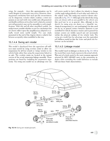
15.1.4.4 Swing arm model haviour can be included.
This model is developed from the equivalent roll stiff- 15.1.4.5 Linkage model
ness mass model by using revolute joints to allow the
suspensions for all four wheels to ‘swing’ relative to the The model based on linkages as shown in Fig. 15.1-10 is
vehicle body rather than using the suspensions linked on the model that most closely represents the actual vehicle.
an axle. The revolute joints are located at the instant This sort of vehicle model is the most common approach
centres of the actual suspension linkage assembly. These adopted by MSC.ADAMS users in the automotive in-
positions are found by modelling the suspensions sepa- dustry often extending the model definition to include
rately. The swing arm model has an advantage over the full non-linear bush characteristics.
Spring
Spring damper
damper
Rear left
REV swing arm
REV
Rear right
swing arm Spring
damper
Spring
damper REV REV
REV
Front left
Front right swing arm
swing arm and wheel knuckle
REV and wheel knuckle
Fig. 15.1-9 Swing arm model approach.
481