Page 478 - Automotive Engineering Powertrain Chassis System and Vehicle Body
P. 478

CHAP TER 1 5. 1       Modelling and assembly of the full vehicle


                                         Traditional leaf spring


                                         Simple equivalent spring model


                                         SAE 3-link model                     Bush


                                                                  Link
                                                    Link
                                                                               Link


                                         Lumped mass/beam elements
                                                                                Bush


                                                  Masses                     Beams


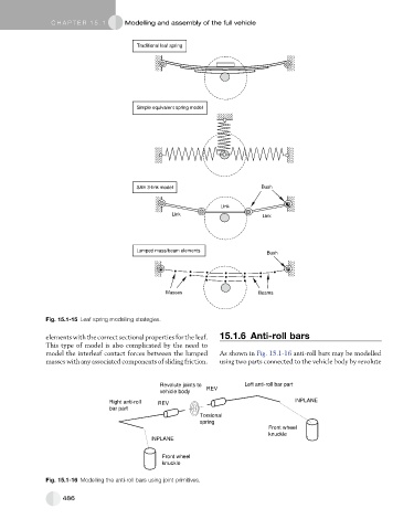
               Fig. 15.1-15 Leaf spring modelling strategies.


               elements with the correct sectional properties for the leaf.  15.1.6 Anti-roll bars
               This type of model is also complicated by the need to
               model the interleaf contact forces between the lumped  As shown in Fig. 15.1-16 anti-roll bars may be modelled
               masses with any associated components of sliding friction.  using two parts connected to the vehicle body by revolute


                                                Revolute joints to       Left anti-roll bar part
                                                vehicle body  REV
                                 Right anti-roll  REV                                   INPLANE
                                 bar part
                                                            Torsional
                                                            spring
                                                                                Front wheel
                                                                                knuckle
                                              INPLANE

                                                 Front wheel
                                                 knuckle

               Fig. 15.1-16 Modelling the anti-roll bars using joint primitives.


                    486
   473   474   475   476   477   478   479   480   481   482   483