
Page 481 - Automotive Engineering Powertrain Chassis System and Vehicle Body
P. 481
Modelling and assembly of the full vehicle C HAPTER 15.1
REVOLUTE
Bell crank
Rebound movement REVOLUTE
UNIVERSAL
Spring damper
Bump movement
Anti-roll bar SPHERICAL
Push rod
upper
Rotational spring damper REVOLUTE
Push rod
Anti-roll bar
lower Rotation
REVOLUTE
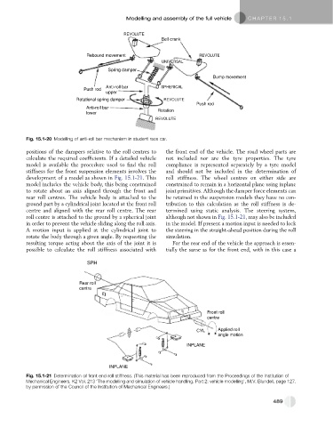
Fig. 15.1-20 Modelling of anti-roll bar mechanism in student race car.
positions of the dampers relative to the roll centres to the front end of the vehicle. The road wheel parts are
calculate the required coefficients. If a detailed vehicle not included nor are the tyre properties. The tyre
model is available the procedure used to find the roll compliance is represented separately by a tyre model
stiffness for the front suspension elements involves the and should not be included in the determination of
development of a model as shown in Fig. 15.1-21. This roll stiffness. The wheel centres on either side are
model includes the vehicle body, this being constrained constrained to remain in a horizontal plane using inplane
to rotate about an axis aligned through the front and joint primitives. Although the damper force elements can
rear roll centres. The vehicle body is attached to the be retained in the suspension models they have no con-
ground part by a cylindrical joint located at the front roll tribution to this calculation as the roll stiffness is de-
centre and aligned with the rear roll centre. The rear termined using static analysis. The steering system,
roll centre is attached to the ground by a spherical joint although not shown in Fig. 15.1-21, may also be included
in order to prevent the vehicle sliding along the roll axis. in the model. If present a motion input is needed to lock
A motion input is applied at the cylindrical joint to the steering in the straight-ahead position during the roll
rotate the body through a given angle. By requesting the simulation.
resulting torque acting about the axis of the joint it is For the rear end of the vehicle the approach is essen-
possible to calculate the roll stiffness associated with tially the same as for the front end, with in this case a
SPH
Rear roll
centre
Front roll
centre
CYL Applied roll
angle motion
INPLANE
INPLANE
Fig. 15.1-21 Determination of front end roll stiffness. (This material has been reproduced from the Proceedings of the Institution of
Mechanical Engineers, K2 Vol. 213 ‘The modelling and simulation of vehicle handling. Part 2: vehicle modelling’, M.V. Blundell, page 127,
by permission of the Council of the Institution of Mechanical Engineers.)
489