
Page 485 - Automotive Engineering Powertrain Chassis System and Vehicle Body
P. 485
Modelling and assembly of the full vehicle C HAPTER 15.1
Weight transfer
z
Deceleration
Brake torque
x Brake torque
Fxbr Fxbf
Fzr Fzf
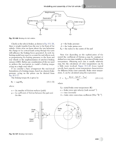
Fig. 15.1-26 Braking of a full vehicle.
Clearly as the vehicle brakes, as shown in Fig. 15.1-26, p ¼ the brake pressure
there is weight transfer from the rear to the front of the A ¼ the brake piston area
vehicle. Given what we know about the tyre behaviour R d ¼ the radius to the centre of the pad
the change in the vertical loads acting through the tyres
will influence the braking forces generated. As such the
braking model may need to account for real effects such Note that depending on the sophistication of the
as proportioning the braking pressures to the front and model the coefficient of friction m may be constant or
rear wheels or the implementation of anti-lock braking defined as a run-time variable as a function of brake rotor
systems (ABS). Before any consideration of this we need temperature. Obtaining such data is usually relatively
to address the mechanism to model a braking torque easy, but the calculation of rotor temperature can be
acting on a single road wheel. a little more involved. Figure 15.1-28 shows typical
If we consider a basic arrangement the mechanical specific heat capacity versus temperature characteristics
formulation of a braking torque, based on a known brake for different brake rotor materials. Brake rotor temper-
pressure, acting on the piston can be derived from ature, T, can be calculated using the expression:
Fig. 15.1-27.
The braking torque B T is given by T ¼ T 0 þ B T ut hA c ðT T env Þ (15.1.14)
mc
B T ¼ nmpAR d (15.1.13)
where
where
T 0 ¼ initial brake rotor temperature (K)
1
n ¼ the number of friction surfaces (pads) u ¼ brake rotor spin velocity (rads second )
m ¼ he coefficient of friction between the pads and t ¼ time (seconds)
2 1
the disc h ¼ brake rotor convection coefficient (Wm K )
B T
F R
Brake R
Brake disc d
pad
P
F N
A
Brake
piston
Fig. 15.1-27 Braking mechanism.
493