
Page 480 - Automotive Engineering Powertrain Chassis System and Vehicle Body
P. 480
CHAP TER 1 5. 1 Modelling and assembly of the full vehicle
Interconnecting finite
element type beam elements
Distributed bodies with
lumped masses
UNIVERSAL
REV/BUSH
REV/BUSH
Drop link
UNIVERSAL
Drop link
SPHERICAL
SPHERICAL
Fig. 15.1-18 Modelling the anti-roll bars using interconnected finite element beams.
the chassis by a revolute joint. The revolute joint allows damping in roll compared to damping in heave. Such
the anti-roll bar to rock back and forward as the bell ‘three spring’ systems are common in higher formula
cranks rotate during parallel wheel travel but prevents motorsports events when allowed by the rules.
rotation during opposite wheel travel when the body
rolls. As the body rolls the torsional stiffness of the anti- 15.1.7 Determination of roll
roll bar, modelled with the rotational spring damper, stiffness for the equivalent roll
resists the pushing motion of one push rod as the sus-
pension moves in bump on one side and the pulling stiffness model
motion as the suspension moves in rebound on the other
side. The small spring damper helps to locate the anti-roll In order to develop a full vehicle model based on roll
bar with respect to the vehicle chassis and adds to the stiffness it is necessary to determine the roll stiffness
heave stiffness and damping. Alternative linkage designs and damping of the front and rear suspension elements
are possible that allow the use of a translational spring separately. The estimation of roll damping is obtained
element and hence allow independent control of by assuming an equivalent linear damping and using the
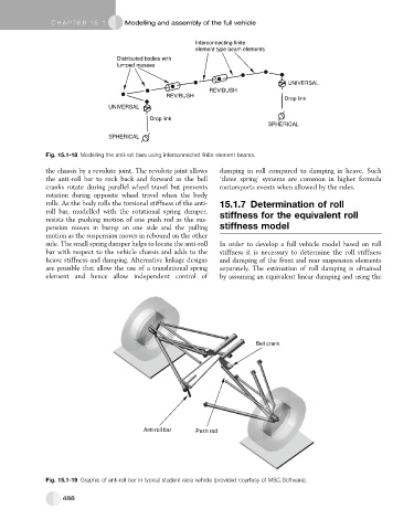
Bell crank
Anti-roll bar Push rod
Fig. 15.1-19 Graphic of anti-roll bar in typical student race vehicle (provided courtesy of MSC.Software).
488