
Page 482 - Automotive Engineering Powertrain Chassis System and Vehicle Body
P. 482
CHAP TER 1 5. 1 Modelling and assembly of the full vehicle
cylindrical joint located at the rear roll centre and In a similar manner the contribution to the roll stiff-
a spherical joint located at the front roll centre. ness at one end of the vehicle due to an anti-roll bar can
For both the front and rear models the vehicle body be determined as shown in Fig. 15.1-24.
can be rotated through an appropriate angle either side of In this case if the ends of the anti-roll bar are separated
the vertical. For the example vehicle used in this text the by a distance L r and the vehicle rolls through an angle f,
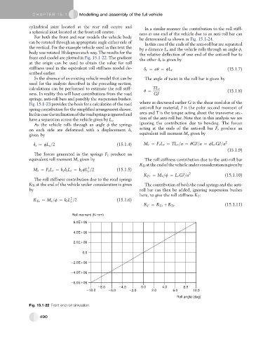
body was rotated 10 degrees each way. The results for the the relative deflection of one end of the anti-roll bar to
front end model are plotted in Fig. 15.1-22. The gradient the other d r is given by
at the origin can be used to obtain the value for roll
stiffness used in the equivalent roll stiffness model de- d r ¼ aq ¼ fL r (15.1.7)
scribed earlier.
In the absence of an existing vehicle model that can be The angle of twist in the roll bar is given by
used for the analysis described in the preceding section,
calculations can be performed to estimate the roll stiff- q ¼ TL r (15.1.8)
ness. In reality this will have contributions from the road GJ
springs, anti-roll bars and possibly the suspension bushes.
Fig. 15.1-23 provides the basis for a calculation of the road where as discussed earlier G is the shear modulus of the
spring contribution for the simplified arrangement shown. anti-roll bar material, J is the polar second moment of
Inthiscasetheinclinationofthe roadspringsisignoredand area and T is the torque acting about the transverse sec-
have a separation across the vehicle given by L s . tion of the anti-roll bar. Note that in this analysis we are
As the vehicle rolls through an angle f the springs ignoring the contribution due to bending. The forces
acting at the ends of the anti-roll bar F r produce an
on each side are deformed with a displacement d s
given by equivalent roll moment M r given by
d s ¼ fL s =2 (15.1.4) M r ¼ F r L r ¼ TL r =a ¼ qGJ=a ¼ fL r GJ=a 2
(15.1.9)
The forces generated in the springs F s produce an
equivalent roll moment M s given by The roll stiffness contribution due to the anti-roll bar
K Tr at the endof thevehicle under consideration is givenby
2
M s ¼ F s L s ¼ k s d s L s ¼ k s fL =2 (15.1.5)
s
K Tr ¼ M r =f ¼ L r GJ=a 2 (15.1.10)
The roll stiffness contribution due to the road springs
K Ts at the end of the vehicle under consideration is given The contribution of both the road springs and the anti-
by roll bar can then be added, ignoring suspension bushes
here, to give the roll stiffness K T :
2
K Ts ¼ M s =f ¼ k s L =2 (15.1.6)
s
K T ¼ K Ts þ K Tr (15.1.11)
Roll moment (N mm)
6.0E 06
4.0E 06
2.0E 06
0.0
2.0E 06
4.0E 06
6.0E 06
8.0 4.0 0.0 4.0 8.0
10.0 6.0 2.0 2.0 6.0 10.0
Roll angle (deg)
Fig. 15.1-22 Front end roll simulation.
490