
Page 479 - Automotive Engineering Powertrain Chassis System and Vehicle Body
P. 479
Modelling and assembly of the full vehicle C HAPTER 15.1
joints and connected to each other by a torsional spring Note that the length L used in equation (15.1.3) is the
located on the centre line of the vehicle. In a more detailed length of the bar subject to twisting. For the configuration
model the analyst could include rubber bush elements shown in Fig. 15.1-17 this is the transverse length of the
rather than the revolute joints shown to connect each side anti-roll bar across the vehicle and does not include the
of the anti-roll bar to the vehicle. In this case for a cylin- fore–aft lengths of the system that connect to the drop
drical bush the torsional stiffness of the bush would be links. These lengths of the bar provide the lever arms to
zero to allow rotation about the axis, or could have a value twist the transverse section of bar and are subject to
associated with the friction in the joint. In this model the bending rather than torsion. An externally solved FE
connection of the anti-roll bars to the suspension system is model could be used to give an equivalent torsional stiff-
not modelled in detail, rather each anti-roll bar part is ness for a simplified representation such as this.
connected to the suspension using an inplane joint prim- Given that bending or flexing of the roll bar may have an
itive that allows the vertical motion of the suspension to influencethenextmodelling refinementoftheanti-rollbar
be transferred to the anti-roll bars and hence produce system uses finite element beams to interconnect a series
a relative twisting motion between the two sides. of rigid bodies with lumped masses distributed along the
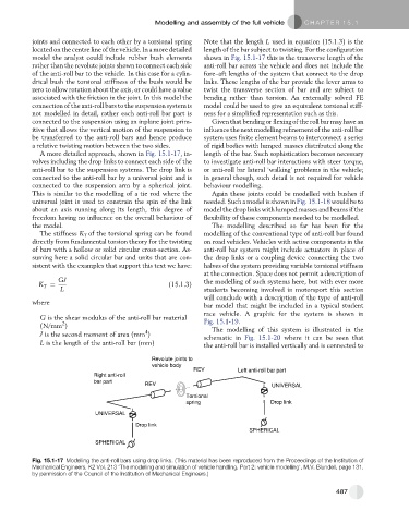
A more detailed approach, shown in Fig. 15.1-17, in- length of the bar. Such sophistication becomes necessary
volves including the drop links to connect each side of the to investigate anti-roll bar interactions with steer torque,
anti-roll bar to the suspension systems. The drop link is or anti-roll bar lateral ‘walking’ problems in the vehicle;
connected to the anti-roll bar by a universal joint and is in general though, such detail is not required for vehicle
connected to the suspension arm by a spherical joint. behaviour modelling.
This is similar to the modelling of a tie rod where the Again these joints could be modelled with bushes if
universal joint is used to constrain the spin of the link needed. Such a model is shown in Fig. 15.1-18 would be to
about an axis running along its length, this degree of model the drop links with lumped masses and beams if the
freedom having no influence on the overall behaviour of flexibility of these components needed to be modelled.
the model. The modelling described so far has been for the
The stiffness K T of the torsional spring can be found modelling of the conventional type of anti-roll bar found
directly from fundamental torsion theory for the twisting on road vehicles. Vehicles with active components in the
of bars with a hollow or solid circular cross-section. As- anti-roll bar system might include actuators in place of
suming here a solid circular bar and units that are con- the drop links or a coupling device connecting the two
sistent with the examples that support this text we have: halves of the system providing variable torsional stiffness
at the connection. Space does not permit a description of
GJ the modelling of such systems here, but with ever more
K T ¼ (15.1.3)
L students becoming involved in motorsport this section
will conclude with a description of the type of anti-roll
where
bar model that might be included in a typical student
race vehicle. A graphic for the system is shown in
G is the shear modulus of the anti-roll bar material Fig. 15.1-19.
2
(N/mm ) The modelling of this system is illustrated in the
4
J is the second moment of area (mm ) schematic in Fig. 15.1-20 where it can be seen that
L is the length of the anti-roll bar (mm) the anti-roll bar is installed vertically and is connected to
Revolute joints to
vehicle body
REV Left anti-roll bar part
Right anti-roll
bar part
REV UNIVERSAL
Torsional
spring Drop link
UNIVERSAL
Drop link
SPHERICAL
SPHERICAL
Fig. 15.1-17 Modelling the anti-roll bars using drop links. (This material has been reproduced from the Proceedings of the Institution of
Mechanical Engineers, K2 Vol. 213 ‘The modelling and simulation of vehicle handling. Part 2: vehicle modelling’, M.V. Blundell, page 131,
by permission of the Council of the Institution of Mechanical Engineers.)
487