
Page 475 - Automotive Engineering Powertrain Chassis System and Vehicle Body
P. 475
Modelling and assembly of the full vehicle C HAPTER 15.1
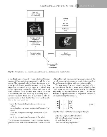
Start with
desired vehicle
characteristics
Trailing
arm
Double
wishbone
McPherson
strut
Using a concept
suspension
system find desired
suspension
characteristics
Run optimization Select
in MSC.ADAMS suspension type
Suspension with
desired
characteristics
Fig. 15.1-11 Application of a concept suspension model (provided courtesy of MSC.Software).
a simulated manoeuvre and a representation of the sus- obtained through experimental rig measurements, if the
pension stiffness and damping acting through the wheel vehicle exists and is to be used as a basis for the model, or
centre. The magnitude of the change in steering wheel by performing simulation with suspension models.
angle Dv will depend on either an open loop fixed time The movement of the suspension due to elastic effects
dependent rotational motion input or a closed loop is dependent on the forces acting on the wheel. In their
torque input using a controller to feed back vehicle po- 1992 paper Scapaticci and Minen describe the relation-
sition variables so as to steer the vehicle to follow ship using the equation shown in (15.1.1) where the
a predefined path. The modelling of steering inputs is functional dependencies due to suspension compliance
discussed in more detail later in this chapter. The de- are defined using the matrix F E :
pendent variables that dictate the position and orienta-
tion of the road wheel are: 2 3 2 32 3
Dx Fxt
6 Dy 7 6 76 Fxb 7
Dx is the change in longitudinal position of the 6 7 ¼ 6 F 76 7 (15.1.1)
wheel 4 Dd 5 4 E 54 Fy 5
Dy is the change in lateral position (half-track) of the Dg Mz
wheel
Dd is the change in steer angle (toe in/out) of the and the inputs are the forces acting on the tyre:
wheel Fxt is the longitudinal tractive force
Dg is the change in camber angle of the wheel
Fxb is the longitudinal braking force
The functional dependencies that dictate how the sus- Fy is the lateral force
pension moves with respect to the input variables can be Mz is the self-aligning moment
483